EM Test PFS 200N Overview
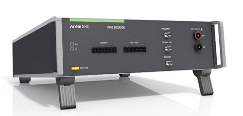
The EM Test PFS 200N automotive power fail simulator is used to comply with standard requirements, mainly from vehicle manufacturers, to perform fast voltage dips ad drops (micro-interruptions). Some standards specify very fast rise and fall times below 1 microsecond an electronic switch.
Testing of electronic modules in 12V/24V or 42V supply systems. Short-term interruptions, micro dips and voltage drop out are causing malfunctions in electronic modules. These phenomena are simulated by the PFS 200N power fail generator. The PFS 200 can be used as an individual instrument or can be used in combination with all other generators of the series 200.
Benefits
The EM Test PFS 200N is a standalone tester providing an electronic switch to perform voltage dips and drops (micro-interruptions) with fast rise and fall times of 1 microsecond. For voltage dips two DC voltage supplies are required while for for voltage drops (micro-interruptions) only one DC voltage supply is needed. The PFS 200N has the ability to control one external DC voltage source by means of an analog DC signal. The PFS 200N can also be easily integrated into a complete test set-up. Operation is possible both manually and by software via USB or GPIB. Fail inputs allow to control an ongoing test sequence based on the status of the DUT. Pre-programmed Standard Test routines allow highest user convenience. Still the PFS 200N offers the Quick Start test routine where parameters can be changed on-line during a test to evaluate the susceptibility level of an individual DUT.
Software
ISO.CONTROL - SOFTWARE FOR CONTROL AND DOCUMENTATION
Outstanding user convenience, clearly structured windows and operation features and the EM TEST standards library along with the flexibility to generate user specific test sequences very easily are the main features of iso.control software. The software is automatically configured according to the connected EM TEST generators. iso.control software covers international/national standards and most of the manufacturer standards and is continuously updated. Extensive reporting capabilities help the user to create test reports that meet international requirements. iso.control is supported by Windows XP, Windows Vista, Windows 7 and Windows 8. Remote control is achieved either via USB or GPIB. iso.control supports a wide range of GPIB cards of National Instruments.
EASY TO OPERATE
Front panel menu and function keys enable the user to program his test routines quickly and accurately. The cursor allows fast control of all test parameters of the programmed routine, thus test procedures are simplified and confidence is generated that every step is carried out correctly.
[split]
Operating Functions
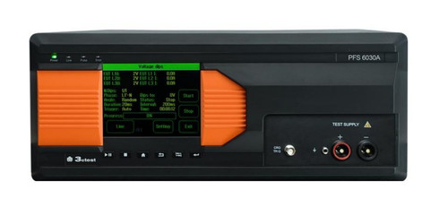
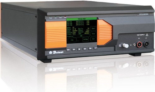
Front Panel |
|
 |
|
| 1 | Display All functions and parameters are displayed (8 lines with max. 40 characters). |
6 | Exit Pressing of the “EXIT” function will cause a reset of the firmware. This is only possible if no test routine is running. |
| 2 | Function keys “F1 .. F7” Parameters and functions, displayed in the lowest line, can be selected with the related function key. |
7 | ESC When pressing the ESC button the user moves back one page in the menu. |
| 3 | Test On By pressing the key “TEST ON” the test procedure is initiated with the preselected parameters. The yellow key is illuminated in TEST ON mode. |
8 | BNC CRO Trigger At the BNC plug CRO TRIGGER a signal is available to trigger an oscilloscope. (5V ?_ neg slope at ervent) |
| 4 | Knob (Inc / Dec) The knob increments or decrements test parameters with a numeric value or selects from a list of parameters. |
9 | LED channel mode The actual channel under control is indicated by LED. |
| 5 | Cursor keys Parameters and functions can be changed on-line. The selection of these parameters is realized with the cursor moving to the left or to the right. |
10 | EUT test supply The EUT is powered via the safety laboratory plugs at the front panel of the simulator. The nominal battery supply depend on the PFS200 model. |
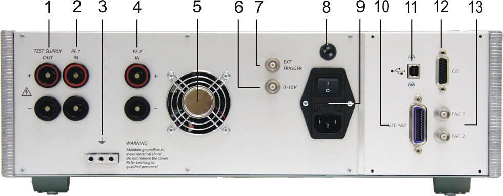
Rear view |
|
 |
|
| 1 |
Test supply output |
8 | Mains selector Selection 115V / 230V. |
| 2 |
Test supply PF1 |
9 | Power on switch The switch is part of the mains filter. Mains fuses are part of the filter 230V/1A or 115V/2A |
| 3 | Reference ground connection | 10 |
Parallel interface
|
| 4 | Test supply PF2 The power supply for the EUT is connected to the banana connectors + / - . The power supply is connected to channel PF2. See par. 4 and 5 for connecting diagrams and detailed information. |
11 | USB interface USB interface “USB B” connector. For datatransfer a USB interface is available. The internal RS 232 interface is converted to USB standard. Therefore the user must set the same Baudrate in the device and control software. Using the USB interface the user can have emc problems during burst tests Our experiences says, that usually the computer USB port is disturbed by interference’s. Therefore a high quality USB cable ( USB 2.0 standard) must be used. |
| 5 |
Ventilation
|
12 | CN interface Device internal interface not used |
| 6 | Control voltage 0-10V The voltage is used to control external power sources. The source normally is connected to the channel PF2. The voltage level can be selected via the operating panel of the PFS. |
13 | Fail detection FAIL 1 (TEST STOP) The BNC input FAIL 1 can be used for failure detection at the EUT. If the input is set to ground (chassis) the PFS-generator will be stopped and the actual test routine is finished. It is not possible to continue this test routine. A complete restart of the routine is necessary. A message of FAIL 1 is indicated in the LCD display as well as in the ISM software. Fail detection FAIL 2 (TEST PAUSE) The BNC input FAIL 2 can be used for failure detection at the EUT. If the input is set to ground (chassis) the actual test routine is paused as long as the low level signal is available at the FAIL 2 input. Without the low level signal the test procedure continues automatically. A message of FAIL 2 is indicated in the LCD display as well as in the ISM software. |
| 7 | BNC EXT. TRIGGER One single event can be released. Trigger level +5 to +15V positive going. |
| Technical Data | |||||
| Power switches PFS200N Series | |||||
| Model | PFS200N30 | PFS200N50 | PFS200N100 | PFS200N150 | PFS200N200 |
| Channel PF1/PF2 | DC voltage max. 80 V | ||||
| Channel PF1 | DC current max. 32 A | DC current max. 50 A | DC current max. 100 A | DC current max. 150 A | DC current max. 200 A |
| Channel PF2 | DC current max. 50 A | DC current max. 100 A | DC current max. 150 A | DC current max. 200 A | |
| Switching time (on/off) | Open circuit < 1µs | ||||
| Inrush current | 70 A 500 ms | 100 A 500 ms | 150 A 500 ms | ||
| electronically overload protection protected against short circuit | Settable up to 32 A |
100 A 500 ms Settable up to 50 A |
150 A 500 ms Settable up to 100 A |
Settable up to 150 A |
Settable up to 200 A |
| Trigger | |||||
| Automatic | automatic release of the events | ||||
| Repetition rate | 0.1 s – 999 s | ||||
| Drop out duration td | .0µs - 9999ms | ||||
| Dip duration | 0.001ms – 1.00 ms step 0.001 ms | ||||
| Manual | Single event trigger | ||||
| External | Trigger by external signal | ||||
| Measurement | |||||
| BNC connector CRO I | internal current sensor for nominal current, inrush current 10mV / A max. 700A | ||||
| BNC connector CRO TRIGGER | trigger for oscilloscope positive ramp to +15V delay approx. 30ms | ||||
| Test routines | |||||
| Quick Start | All parameters adjustable while test is running | ||||
| Standard test Routines | 1. Chrysler PF 9326 2. Ford 3. PSA / Renault |
||||
| Service | Addresses Selftest Set-up |
||||
| Interfaces | |||||
| Serial Interface | USB Setting Baudrate (RS232: 9'600 , 19'200 Baud ) | ||||
| Parallel Interface IEEE | Addresses 1 – 30 | ||||
| Analogue output | 0 – 10V DC to control external voltage sources | ||||
| General | |||||
| Device | PFS 200N30,N50,N100 PFS 200N150, N200 | ||||
| Dimensions | 19” / 3 HU 19” / 6 HU | ||||
| Weight | N30 / N50: 10.8 kg N100: 14kg approx. 30 kg | ||||
| Power supply | 115/230V +10/-15% 50/60Hz (optional 115 V) Max. 60 VA |
||||
| Fuses | 2 * 1 A T | ||||
| Environmental conditions | |||||
| Temperature | 10 °C to 35 °C | ||||
| Humidity | 30 % to 70 %; non condensing Environmental conditions | ||||
| Atmospheric pressure | 86 kPa (860 mbar) to 106 kPa (1 060 mbar) | ||||


