


Overview
Assignment of Polarisation Planes
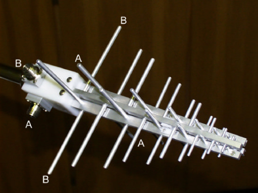
The XSLP 9143 has two orthogonal polarisation planes, which can be accessed independantly via N-connectors. The assignment of the Nconnector to the corresponding polarisation plane is shown in the above picture. The Inner conductor of the N-connector stands always perpendicular on the corresponding polarisation plane. Example: Connector "B" should be used for horizontal polarisation. The antenna is rotated around its longitudinal axis until the elements assigned with "B" are horizontal. The connector "B" faces either upwards or towards ground.
Decoupling of the Polarisation Planes
Although the two polarisation planes are exactly orthogonal to each other, there is no 100% decoupling between them. A horizontal polarised field contributes also to the indication of the vertical polarised antenna section, but with reduced effect. Typical decoupling values for the cross polarised fieldstrength indication are 15 to 20 dB. The decoupling of the polarisation planes depends a lot on environmental reflections. Best decoupling results can be achieved under free-space conditions. The cross polarisation decoupling decreases at higher frequencies due to the element displacement at the antenna tip, which approaches to the element length itself.
Equality of Polarisation Planes
Small differences between the polarisation planes are recognizable for construction reasons. The feeding point distance to the active element is somewhat different. Normally the deviations between the planes are less than 1 dB, as worst case 1.5 dB difference can be assumed. Especially at higher frequencies and for best accuracy it is recommended to use the data which is explicitly assigned to the respective polarisation plane (Sections A or B).
General Hints
For highest accuracy requirements a suitable fixed attenuator (3 dB to 10 dB) may be useful under certain circumstances. Inserting a fixed attenuator at the antenna terminal improves impedance matching, but also reduces the gain and increases the antenna factor by the attenuation value. With an SWR < 2 the attenuator may be omitted in most applications. Antenna measurements in the microwave frequency range suffer from environmental reflections, which may even occur at nonmetallic surfaces as e.g. plastic. Therefore it is recommended to avoid large mast adapters and other big parts in the near surrounding of the antenna.
Antenna reference point
The phase center was used as antenna reference point during calibration. The phase center position is located near the element in half-wave resonance. Example: The wavelength at 1 GHz is 30 cm, the corresponding element would be 15 cm long (the location of the phase center is the approx. 12.5 cm behind the antenna tip)
Further Antenna Data
The XSLP 9143 is directly derived from the very popular model USLP 9143. Therefore pattern data, fieldstrength generation data and correction for short measuring distances of the USLP 9143 can be used.
| Specifications | ||
| Type | Linear dual polarized Logarithmic Periodic Broadband Antenna (Aluminium tubing) for Receive and Transmit Applications. | |
| Nominal Frequency Range | 300 MHz. ... 3 GHz | |
| Usable Frequency Range | 250 MHz ... 5.5 GHz | |
| Isotropic Gain | typ.: 4 ... 7 dBi | |
| Antenna Factor | 15 ... 35 ( 42) dB/m | |
| Nominal Impedance | 50 W | |
| Standing Wave Ratio SWR typical | 1.5 - 3 | |
| Front to Back Ratio | > 15 dB | |
| Cross Polarisation Rejection | typ. 15-25 dB | |
| 3 dB Beamwidth typ. (E-Plane) | 50°-80° | |
| 3 dB Beamwidth typ. (H-Plane) | 90°-170° | |
| Max. Input Power | 100 W (intermitt.) 50 W (cont.) | |
| N-Connectors Female | ||
| Mount | 22 mm Tube, Indexing Ring | |
| Width x Length x Thickness | 540 x 695 x 540 mm | |
| Weight | 1.2 kg | |


