


Overview
The ETS-Lindgren Model 3148 Log Periodic Dipole Array is a linearly polarized, broadband antenna designed to operate over the frequency range of 200 MHz to 2 GHz. The choice of scaling factors, the various diameters of each element, and the center-to center spacing of the booms are such that excellent VSWR characteristics are obtained throughout the operating frequency range (See Model 3148 VSWR data in the “Typical Data” section of this manual). The precise design of the feed and positioning of the elements on the boom yield optimum phase relationship. This causes the active region, at any given frequency, to propagate RF energy towards the smaller elements leaving the elements behind it electrically dead.
The Model 3148 antenna fully satisfies CISPR-16 crosspolarization rejection requirement, and has better than 20 dB crosspolarization rejection below 1000 MHz. The constant gain of the antenna yields an antenna factor which varies linearly with frequency as shown in the “Typical Data” section of this manual. The variation is smooth; therefore, accurate interpolation of performance between specified frequency points is simple.
The Model 3148 Log-Periodic antenna is constructed of lightweight, corrosion-resistant aluminum, providing years of trouble-free indoor and outdoor service.
The antenna is provided with an integral mount and the necessary attachments to mount the antenna to either a tripod (with a ¼-20 threaded mount) or an ETS-Lindgren antenna mast. Individual antenna calibration data is included with each antenna.
The Model 93148 is a non-characterized version of the Model 3148. Should calibration/characterization be desired please contact our calibration department.
STANDARD CONFIGURATION
- Antenna
- Manual
- Individually calibrated at 1m per SAE ARP 958 and 3 and 10m per ANSI C63.5. Actual antenna factors and a signed Certificate of Calibration Conformance included.
OPTIONS
Support Rod: Antenna mount with insert configured to accept EMCO or other tripods with standard ¼ in x 20 threads.
Tripods: ETS-Lindgren offers two nonmetallic, non-reflective tripods for use at both indoor and outdoor EMC test sites.
The Model 4-TR, constructed of linen phenolic and delrin, is designed with an adjustable center post for precise height adjustments. Maximum height for the 4-TR is 2.0 m (80.0 in), while minimum height is 94 cm (37.0 in). This tripod can support up to an 11.8 kg (26.0 lb) load.
The 7-TR tripod has several different configurations, including options for manual or pneumatic polarization. This tripod provides increased stability for physically large antennas. Its unique design allows for quick assembly/disassembly and convenient storage. Quick height adjustment and locking wheels provide ease of use during testing. This tripod can support up to a 13.5 kg (30.0 lb) load. For the 7-TR series, maximum height is 2.17 m (85.8 in), with a minimum height of .8 m (31.8 in). The 7-TR is constructed of PVC and fiberglass components.
MOUNTING INSTRUCTIONS
The Model 3148 Antenna consists of the following:
1 ea. Log Periodic Dipole Array Antenna
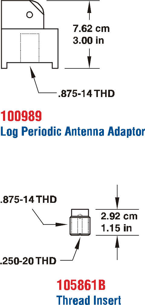
1 ea. Log Periodic Antenna Adaptor
1 ea. Thread Insert for the Adaptor
ANTENNA SUPPORTS
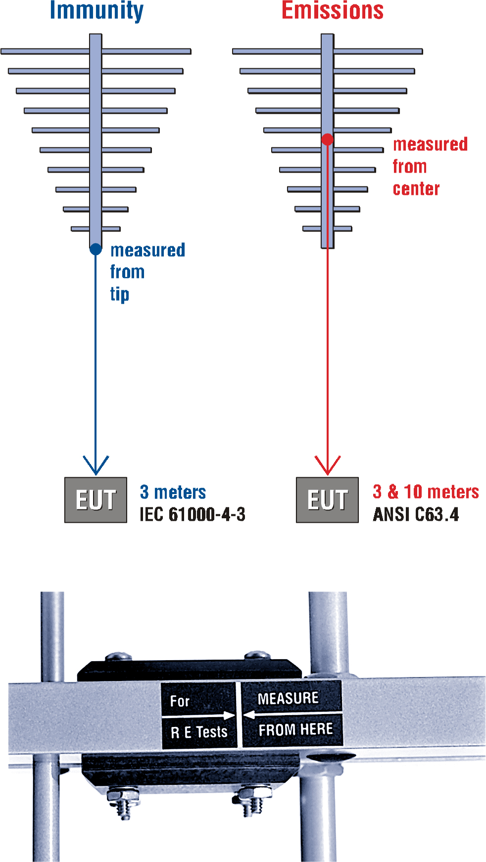
| EMISSIONS AND IMMUNITYThe picture and diagrams below illustrate the convenient label that pinpoints the antenna’s centerline and tip, serving as a reminder of where to perform measurements.
|
APPLICATION
Install the Model 3148 on an ETS-Lindgren tripod or antenna mast adapter. Connect an N-type coaxial cable from the antenna connector to a generator (immunity) or receiver (emissions). Both horizontal and vertical polarization are easily accomplished when the Model 3148 is mounted on a tower or tripod. Contact with any metallic or non-metallic structure can capacitively load the antenna which may cause inconsistent results. Therefore, care must be taken to ensure that no part of the dipole elements are in contact with the tripod or tower, particularly in vertically-polarized tests. Where possible, run the feed cable straight at least 1 meter or more back from the Model 3148 before dropping vertically.
For emissions measurements, electric field strength in db[V/m] is obtained from
E(dBV/m)=V(dBV)+AF(dB1/m)+a(dB),
Where V is the receiver or spectrum analyzer voltage reading, AF is antenna factor (see attached calibration data), and a is cable loss in dB, if cable losses are non-negligible. For immunity testing, the electric field strength generated at a distance d can be approximated by
d pg E V m 30 ( / )
where d is in meters, g is the numeric gain (10 G[dB]/10, see attached calibration data), and P is antenna net input power in watts. An estimate of the power required in free space condition for any field strength E can be obtained from the forward power graphs in the “Typical Data” section, which shows power required in watts to generate 1 V/m. For any other field strength not shown, multiply the power in watts by the desired E-field squared, or
P(E V/m) = E2 P(1 V/m).
Actual transmitted field strength should be verified using an ETS-Lindgren Model HI-6005 Electric Field Probe or equivalent. For IEC/EN 31000-4-3 type testing, the antenna tip can be placed at any distance between 1 and 3 meters from the EUT as long as the front face plane is illuminated according to the –0, +6 dB uniform field specifications. It is usually necessary to place RF absorbing material between the EUT and antenna to suppress ground plane reflection to ensure the field uniformly, or conduct the immunity test in a fully-lined anechoic room. In general, closer distances require less power to create a given field strength.
TYPICAL DATA
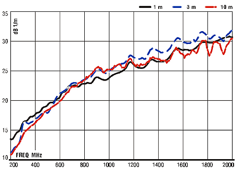 |  |
| Antenna Factor
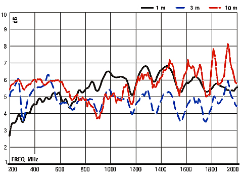
| Gain
|
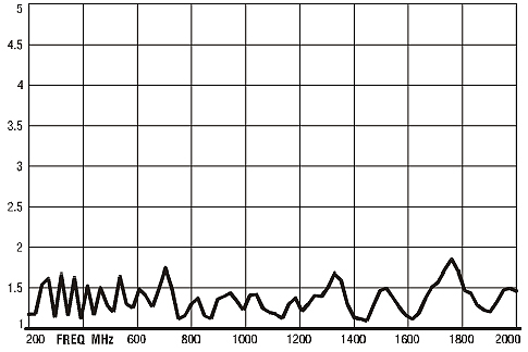 | 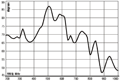 |
| VSWR | Half Power Beamwidth |
| GENERAL SPECIFICATIONS | |
| ELECTRICAL | |
| Frequency Range | 200 MHz – 2 GHz |
| VSWR Ratio | 1.2:1 average 2.0:1 maximum |
| Maximum Continuous Power | 1 kW |
| Peak Power | 1.3 kW |
| Input Impedance (Nominal) | 50 ohms |
| Symmetry | +/- 0.5 dB |
| Cross-Polarization rejection | Better than 20 dB below 1000 MHz |
| Connector | Type N female |
| PHYSICAL | |
| Height | 6.4 cm (2.5 in ) |
| Width | 85.6 cm (33.7 in) |
| Depth | (length) 73.7 cm (29.0 in) |
| Weight | 2.0 kg (4.5 lb) |


