


Overview
CNI 501 1-Phase Coupling Decoupling Network
The single phase coupling/decoupling networks of the CNI 501x-series are used to couple EFT/Burst pulses and Surge pulses on to AC and/or DC supply lines.
Within the range of EM TEST coupling/decoupling networks we offer different models for test voltages from 5kV up to 10kV with DUT currents of 16A, 32A, 63A and 100A (higher current ratings on request) for the various test requirements and equipment configuration.
Benefits
The CNI 501x-series coupling/decoupling networks are built fully complying to the standard requirements of EN/IEC 61000-4-4 and EN/IEC 61000-4-5. Residual voltage levels are carefully considered as well as the value of the decoupling inductors in order to meet the requirements with regard to voltage drop at the rated current of each type of CDN. Apart from the coverage of the EN/IEC 61000-4-5 standard the CNI 501Bx series also fully complies with the surge test requirements outlined in ANSI/IEEE C62.41.
Being fully controlled by the related generators couplings of the CNI 501x-series are set automatically as selected for the test (either by manual operation or via software). When performing surge tests the generators will automatically set the required source impedance depending on the standard and the coupling mode.
Operating Functions
Front Panel | |
 Figure 2.1: CNI 503 font view ( model for 4kV ) | |
| 1 | TEST ON | 6 | DUT Output L1/DC+, L2, L3, N/DC-, PE |
| 2 | Switching ANSI -IEC | 7 | Earth plug for EFT burst verification |
| 3 | EFT output to HFK coupling clamp | 8 | LED display Pulse (EFT / 50? HFK / Surge) |
| 4 | HV output for ext. surge coupling networks | 9 | LED display couplings |
| 5 | COM output for ext. surge coupling networks | 10 | EFT input from UCS 500Mx / EFT 500/800 |
1 Button Test On
Press this button to connect the power mains supply to the EUT via the built in relay switch. The yellow light in the button
indicates the switched mains to the EUT.
2 Button ANSI / IEC (Option)
This button changes the coupling between ANSI coupling and IEC coupling.
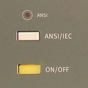 | LED disabled: | IEC coupling | 2Ω L-L or L-N 10Ω L-PE, N-PE |
| LED enabled: | ANSI coupling | 2Ω all couplings |
Rear view | |
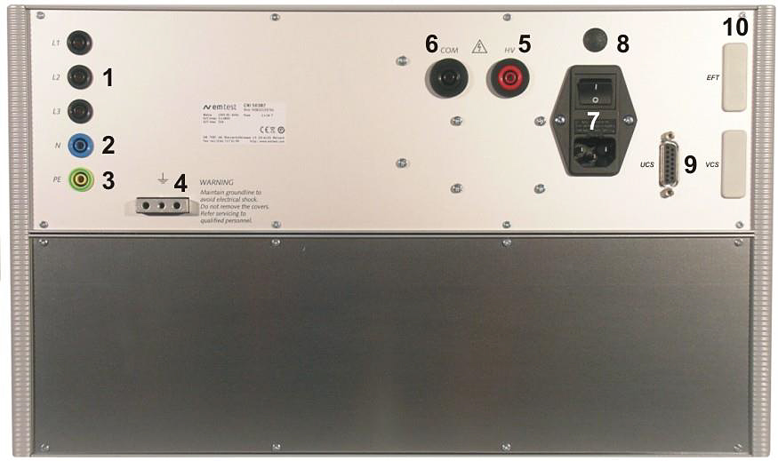 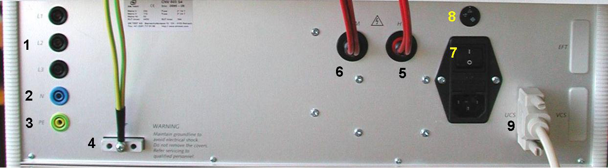 | |
| 1 | EUT power L1, L2, L3 | 5 | HV Input from generator |
| 2 | EUT power N | 6 | COM Input from generator |
| 3 | EUT power PE | 7 | Power switch with fuse |
| 4 | Ground Reference | 8 | Voltage selector 230V / 115V |
| 5 | HV Input from generator | 9 | CN control input from UCS generator |
| 10 | CN control input from EFT and or VCS generator |

Figure 2.3: Front Side CNI 501 S1 with AC / DC Switch

Figure 2.4: CNI 501 S1 Rear Side


