| Typical Antenna Factors and Gain | Typical VSWR |
ETS-Lindgren 3115 Overview
- ASSOCIATED EQUIPMENT
- PERFORMANCE DATA
- SPECIFICATIONS
- ADDITIONAL INFO
| Specifications | |
| Frequency Range | 750 MHz - 18 GHz |
| VSWR (avg) | < 1.5:1 |
| Maximum Continuous Power | 300 W |
| Peak Power | 500 W |
| Impedance | 50 ohms |
| Connector Type | N female (precision) |
| Width | 9.6 in (24.4 cm) (at aperture) |
| Depth | 11.0 in (27.9 cm) |
| Height | 6.2 in (15.9 cm) (at aperture) |
| Weight | 4.0 lb (1.8 kg) |
ETS-Lindgren 3115 Features
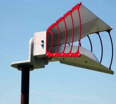
ETS-Lindgren's Model 3115 Double-Ridged Guide Horn Antenna has excellent gain and VSWR characteristics, it is small and portable with a length of 24.4 cm (9.6 in), and is now calibrated to 750 MHz.
 The EMCO/ETS-Lindgren 3115 Double-Ridged Waveguide Horn Antenna is ideally suited for IEC 61000-4-3 and MIL-STD 461G immunity tests and ANSI C63.4 and EN 55022 emissions testing. As a set, this linearly polarized broadband antenna has an average VSWR of less than 1.6 to 1 and cover a multi-octave bandwidth of 1 GHz to 18 GHz. This antenna is specifically designed for EMI measurements, but can also be used for EW, antenna gain and pattern measurement, surveillance, and other applications.
The mounting brackets for Model 3115 is adjustable for changing polarization of the antenna. Standard 1/4 in x 20 threads are used on the mounting brackets of all double-ridge waveguides for mounting on an EMCO tripod or most other tripods. The Model 3115 has excellent gain and VSWR characteristics. This antenna is small and portable with a length of 24.4 cm (9.6 in). The feed system uses a Precision Type N female connector so the antenna can handle considerable power with low losses above 12 GHz.
Ultra Broadband
The model 3115 sweeps from 750 MHz to 18 GHz without stopping for band breaks, making it ideal for automated testing. It has the widest usable frequency range of any antenna in its class, with no performance degradation from high order modes.
Power Input
This horn antenna uses a Type N precision connector and accepts up to 300 watts of continuous input power. The antenna's high gain and low VSWR over its operating frequency translates into efficient amplifier use and higher field strengths.
Construction
An antenna constructed to maximize structural integrity is better able to maintain its electrical properties. The benefits are better measurement repeatability, lower uncertainty values and longer calibration validity. Constructed of powder coated aluminum plate, the 3115 will provide years of trouble-free indoor and outdoor service. This antenna is small and portable with a length of 24.4 cm (9.6 in). This antenna includes a 1/4 in x 20 tripod mount.?
Mounting Instructions
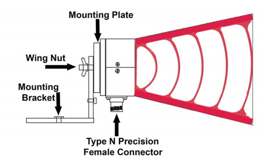
The following instructions allow the user to mount the Model 3115 on an ETS-Lindgren or compatible tripod.
Step 1. For packing purposes, the ETS/EMCO 3115 is shipped with the mounting bracket attached in reverse. Before the antenna may be mounted on a tripod, the user must remove the wing nut and separate the antenna from the mounting bracket.
Step 2. To mount the antenna on a tripod, attach the mounting bracket to the tripod with the ¼-20 bolt provided. Next, attach the antenna to the mounting bracket by fitting the position lock (small posts on the mounting plate) into the indentation provided on the mounting bracket, then tightening the wing nut. To rotate the antenna, loosen the wing nut, reset the antenna in the desired position lock and tighten the wing nuts.
Step 3. After the Model 3115 antenna is mounted onto the tripod or tower, connect a type N coaxial cable from the female antenna connector to a signal generator or amplifier.

Mounting Diagram


