Overview
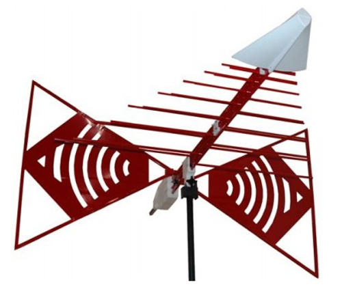
The EMCO ETS-Lindgren 3141 is a popular bow-tie/log periodic combination BiConiLogTM family. A biconilog antenna combines a broadband biconicallike bow-tie antenna with a standard log periodic to replace the traditional use of two antennas in the 30-1000 MHz EMC test frequencies. Many EMC antennas are variations of a standard tuned dipole. For any dipole-type antenna to transmit or receive energy most efficiently, its length must be nearly a half wavelength, which is about 4.6 meters long at 30 MHz, and 2.8 meters long at 50 MHz.
Unfortunately, this is too unwieldy for many anechoic chambers and test sites. The end plates of the Model 3141 T bow-ties make it look like an antenna twice as long as its 1.4 meter length. The result is about a 10 dB improvement in low-frequency transmit gain and receive antenna factor compared to a same-length regular bow-tie. Although bow-ties have been used for all elements on log-periodic antennas in the past, in EMC applications the advantage gained is an extension of the useful low frequency range of the typical LPDA's from 100 MHz down to 30 MHz. At 30 MHz, an efficient single dipole type antenna must be 5 meters long, whereas suitable performance is obtained here with less than a 1.4 meter long bow-tie. A simple wire outline bow-tie antenna is narrowband compared to a sheet bow-tie or biconical, thus struts are added to the Model 3141 bow-ties to better simulate the broadband sheet bow-tie. The standard "self-balun" feed of the log-periodic also provides a matched, balanced feed to the bowtie elements. To prevent cable pickup below 100 MHz, the Model 3141 contains a "balun" which acts as a common-mode choke to keep unbalanced current off the coaxial feed cable outer shield. Even though the Model 3141 is highly balanced (symmetry +/-0.5 dB), in vertically polarized measurements cable position can effect results, so it is recommended that the cable be suspended horizontally back from the antenna at least 1 meter before any vertical drop. Below 150 MHz, bow-tie radiation dominates with a dipole-like pattern, while above 150 MHz the radiation in the plane of the elements is directional.
The antenna has a mounting bracket and 1/4x20 UNC knob for attaching to EMCO tripod and tower adaptors. Individual antenna factor calibration data is included with each antenna. The Model 3141 can be used with or without the end frames of the T bow-ties. However, calibration data is valid ONLY with the T bow-ties intact. The unique feature of the Model 3141 is the T bow-tie elements. A T bow-tie increases the equivalent dipole electrical length, thereby decreasing resonant frequency and increasing efficiency in the 20-60 MHz range. Similarly, a regular bow-tie has a lower resonant frequency than an equal length single-wire dipole. The T bow-tie has its first resonance at a frequency where its length is about 0.22λ, a regular bow-tie at a length of 0.3λ, and a tuned dipole at about a length of 0.48λ. Thus at 50 MHz the 1.4 m long T bow-tie of the Model 3141 behaves like a 2.8 m tuned dipole. Cross-polar radiation is minimized because current flow on one of the T end frames is almost exactly cancelled by the oppositely-phased current on the other T end.
ETS-Lindgren 3141 Specifications:
- Frequency range: 26 MHz to 2000 MHz
- Impedance (nominal): 50 Ω
- Maximum continuous power:
- 26 - 60 MHz: 500 Watts
- 60 - 2000 MHz: 1,000 Watts
- Connector: N type female
- Size antenna (L x H x W in mm): approx. 52.7 in. (133.9 cm) x 66.2 in (168.1 cm) x 30 in (76.2 cm)
- Weight: approx. 8.8 lbs (4 kg)


