Overview
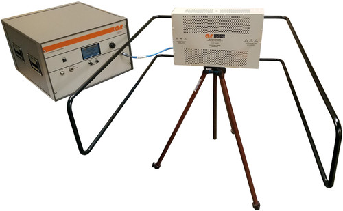
The Amplifier Research SG6000 is a light weight 2U (3.5”) high signal generator with a frequency bandwidth of 100 kHz to 6 GHz. The signal generator offers a comprehensive modulation capability and offers the convenience of control from the front panel and remote communications using either GPIB or RS-232. The signal generator has rear panel connectors for easy installation into a rack mounted system. The
| Specifications | ||||||||||||||||||||||
| Frequency Range | 100 kHz to 6 GHz (Performance below 250 kHz unspecified) | |||||||||||||||||||||
| Resolution | 0.01 Hz | |||||||||||||||||||||
| Phase incrementing | 0.01° Nominal | |||||||||||||||||||||
| Frequency Bands | N is a factor to help define certain specifications in the spec sheet
|
|||||||||||||||||||||
| Switching Speed |
NOTE: Time of receipt of SCPI command or trigger signal to within 0.1ppm of final frequency or within 100 Hz, whichever is greater, and amplitude settled to within 0.2 dB. Additional time may be required for the amplitude to settle within 0.2 dB when switching to or from frequencies < 500 kHz or amplitudes > +5 dBm. |
|||||||||||||||||||||
| Accuracy | ±aging rate ±temperature effects: ±line voltage effects |
|||||||||||||||||||||
| Internal Time base Oscillator aging rate | ≤ ±5 ppm/10 yrs, < ±1ppm/yr | |||||||||||||||||||||
| Temperature effects | ±1ppm (0 to 55°C) | |||||||||||||||||||||
| Line Voltage effects | ±0.1ppm Nominal | |||||||||||||||||||||
| Line Voltage range | 5% to -10% Nominal | |||||||||||||||||||||
| REFERENCE OUTPUT | ||||||||||||||||||||||
| Frequency | 10 MHz | |||||||||||||||||||||
| Amplitude | ≥+4dBm Nominal (into 50? load) | |||||||||||||||||||||
| EXTERNAL REFERENCE INPUT | ||||||||||||||||||||||
| Input Frequency | 10 MHz | |||||||||||||||||||||
| Lock Range | ±1ppm | |||||||||||||||||||||
| Amplitude | >-3.5 to 20 dBm Nominal | |||||||||||||||||||||
| Impedance | 50 Ω Nominal | |||||||||||||||||||||
| RF OUTPUT | Range (Specifications between 20°C and 30°C)
NOTE: Maximum Output Power typically decreases by 0.2 dB/degree C for temperatures outside this range. Resolution..............................................................0.02 dB Nominal Step Attenuator ......................................................0 to 130 dB in 5 dB steps |
|||||||||||||||||||||
| RF OUTPUT CONNECTOR | 50 Ω type N connector | |||||||||||||||||||||
| VSWR | ≤ 1.4 GHz.............................................................1 1.7:1 Typical > 1.4 GHz to 4 GHz.............................................................1 2.3:1 Typical > 4.0 GHz to 5 GHz.............................................................1 2.4:1 Typical > 5 GHz to 6 GHz.............................................................1 2.2:1 Typical |
|||||||||||||||||||||
| MAXIMUM REVERSE POWER | ||||||||||||||||||||||
| DC Voltage (max) | 50 VDC Nominal | |||||||||||||||||||||
| 250 kHz to 6 GHz | 2 W Nominal | |||||||||||||||||||||
| SWITCHING SPEED | (Time from receipt of SCPI command or trigger signal to amplitude settled within 0.2 dB when switching to or from amplitudes < +5 dBm)
|
|||||||||||||||||||||
| ABSOLUTE LEVEL ACCURACY | (between 20°C and 30°C and the ALC on)
|
|||||||||||||||||||||
| ABSOLUTE LEVEL ACCURACY (For temperatures outside of 20°C and 30°C) |
≤ 4.5 GHz............................................................. 0.01 dB/degree C >4.5 GHz............................................................. 0.02 dB/degree C |
|||||||||||||||||||||
| FLATNESS CORRECTION | Number of Points: 1601 Number of Tables: Dependent on available free memory |
|||||||||||||||||||||
| SPECTRAL PURITY | At Single sideband phase noise (at 20 kHz offset) 500 MHz...................................... ≤-126 dBc/Hz typical 1 GHz.......................................... ≤-121 dBc/Hz typical 2 GHz.......................................... ≤-115 dBc/Hz typical 3 GHz.......................................... ≤-110 dBc/Hz typical 4 GHz.......................................... ≤-109 dB/Hz typical 6 GHz.......................................... ≤-104 dB/Hz typical |
|||||||||||||||||||||
| HARMONICS (CW mode, output level <4 dBm) |
≤3 GHz .................................................................< -30dBc >3 GHz ................................................................< -44 dBc typical |
|||||||||||||||||||||
| NON-HARMONICS (CW mode) > 10 kHz offset | 250 kHz to 250 MHz..............................................< -54 dBc >250 MHz to 375 MHz..........................................< -61 dBc >375 MHz to 750 MHz..........................................< -55 dBc >750 MHz to 1.5 GHz...........................................< -48 dBc >1.5 GHz to 3 GHz...............................................< -48 dBc >3 GHz to 6 GHz..................................................≤ -42 dBc |
|||||||||||||||||||||


