AE Techron 7224 Overview
Single-phase, 2U, industrial amplifier
- Field-selectable controlled-voltage or controlled-current operation
- Can be switched between rail supply modes and voltages to optimize for various load impedances
- Protection circuits guard against over/under voltage, over current, over temperature, and circulating ground currents
The AE Techron 7224 amplifier is a 900-VA, DC-enabled unit that provides exceptional versatility and value. It features a DC to 400 kHz small-signal bandwidth and offers a wide range of field-configurable options. In continuous operation, a 7224 can provide 900 watts RMS of output power. If more current or power is needed, up to four amplifiers can be combined in series or parallel and operate as a single system.
The 7224 can be configured by the user for highvoltage/low-current, medium voltage and current, or low-voltage/high-current applications. It provides very low noise and fast slew rates, and can safely drive a wide range of resistive, inductive loads.
The 7224 is typically used to simulate ripple, noise, drop-outs, surges and ground as required by a variety of EMC standards for DC powered electronics like FMC1278, DO-160, and MIL STD 461. It can also be used as a gradient amplifier for very small bore, high-gain MRI and NMR systems.
[split]
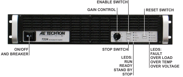
FRONT VIEW
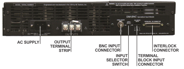
BACK VIEW
AE Techron 7224 Test Standards
- MIL STD 461
- RTCA / DO 160
- AIRBUS ABD0100
- Boeing D6-16050-5
- ISO 1540:2006
- MIL STD 704
- EN 300329
- EN 300340
- EN 300342-1
- EN 301489-1, -7, -17, -24
- ISO 7637
- ISO 11452-8 and -10
- ISO 16750-2
- JASO D001-94
- SAE J1113-2, -11, -12
- SAE J1455
- BMW 600 13.0 (Part 2)
- BMW GS 95004
- BMW GS 95024-2-1
- Chrysler CS-11809 (2009)
- Chrysler CS-11979
- Chrysler DC-11224 Rev.A
- DaimlerChrysler DC-10614
- DaimlerChrysler DC-10615
- DaimlerChrysler DC-11224 DaimlerChrysler PF-10540
- EMC-CS-2010JLR V1.1 (2011-01)
- Fiat 9.90110
- Ford EMC-CS-2009.1, RI 140 and 150
- Ford EMC-CS-2009.1, CI 210, 230, 250 and 260
- Ford ES-XW7T-1A278-AC
- Ford WDR 00.00EA
- Freightliner 49-00085
- GLloyd VI-7-2
- GM 9105P
- GMW 3097
- GMW 3100
- GMW 3172
- Honda 3982z-SDA-0030
- Hyundai ES 39110-00
- Hyundai ES 96100-02
- IVECO 16-2103
- Kia/Hyundai ES 95400-10
- Mack Trucks 606GS15
- MAN 3285
- Mazda MES PW 67600
- MBN 10284-2
- Mercedes MBN 10284-2
- Mercedes AV EMV
- Mercedes-Benz A 211 000 42 99
- Mercedes MBN 22100-2
- Mitsubishi ES-X82010
- MW 3097
- Nissan 28400 NDS 02, 03, 05, 07
- Nissan 28401 NDS 02
- Piaggio 7431
- Porsche
- PSA B21 7090 & 7110
- PSA B21 7110
- Renault 36.00.400/B & C
- Renault 36.00.808/--D, E.F, G, H, J, K, and L
- SA B21 7110
- Scania TB1400
- Scania TB1700
- Smart DE1005B
- Tata TST/TS/WI/257
- Toyota TSC3500G
- Toyota TSC3590G
- Toyota TSC6203G
- Toyota TSC7001G
- Toyota TSC7034G
- UN ECE R10 (Automotive)
- Volvo STD 515-0003
- Volvo EMC Requirements
- VW TL 801 01
- VW TL 820 66
- VW TL 821 66
- VW TL 823 66
- VW TL 824 66
- VW TL 825 66
Installation
The 7224 amplifiers are packaged in a rugged powder-coated aluminum chassis. This chassis is 2U (rack units) tall, and has rack “ears” on each side of the front panel for mounting to a standard EIA (Electronic Industries Association) rack. Use standard rack mounting hardware to mount the amplifier. Use nylon washers if you wish to protect the powder-coat finish on the front of the amplifier.
Optionally, the amplifier can be placed on a bench top; please keep in mind that the protective powder-coating can be scratched when placed on other equipment or on a bench top, especially when there is dirt present. To protect the finish, a set of rubber feet is included in the toolkit that can be installed on the bottom of the amplifier.
Allow ample space on the sides and especially the back of the amplifier for heated air to escape. The amplifier should be mounted in a rack that is adequately ventilated and not sealed. Likewise, the front of the amplifier should be unobstructed to allow cool air to enter the amplifier.
Connecting the Load
Before connecting the amplifier, make sure the AC power cord is unplugged.
This section describes output wiring to the load when using the default amplifier configuration: Single (or Master) amplifier operated in Controlled Voltage mode. The 7224 amplifier also can be field-adjusted for operation in Controlled Current mode or for operation as a Slave amplifier in a multi-amplifier system. These alternate configu - rations may require special output wiring and/or additional components.
If your application requires Controlled Current and/ or Slave operation, change the default settings on the main board before connecting the amplifier.
Connection to the output of the amplifier is to a 3-position terminal strip with #8 screws. Wires terminated with #8 ring terminals, tinned wires up to 10GA in size, or bus bars with 0.18 in. (4.6 mm) holes are recommended when connecting to the output terminals. Connect the load across the terminals marked “OUTPUT” (positive) and “COM” (negative/ground). The third terminal, “CHAS- SIS GROUND” can be connected to an external ground point such as the rack chassis.
Connecting the Load
Always use the appropriate wire size and insula- tion for the maximum current and voltage expected at the output. Never connect the output of the amplifier to any other model amplifier, power sup- ply, signal source, or other inappropriate load; fire can result.
NOTE: The 7224 amplifier comes with a factory-in- stalled 2.7-ohm, 2W, 5%, metal-oxide resistor con- necting the terminals marked “COM and “CHAS- SIS GROUND” (see Figure 2.3) . This resistor should NOT be removed. WARNING: Removing this resistor can cause dangerous output and/ or damage to the load.
Closeup of the Output Terminals
Closeup of SIM card
AE Techron 7224 General Specifications |
|
Performance Testing was done at 100 Hz. Continuous DC power levels are lower. See DC Specifications chart for test conditions. |
|
Frequency Response, DC - 300 kHz (1 watt) | +1.0 to -2.0 dB |
8-Ohm Power Response (continuous duty) | DC to 60 kHz ± 140 Vpk DC to 200 kHz: ± 65 Vpk DC to 350 kHz: ± 45 Vpk |
Slew Rate | 75 V/µSec |
Residual Noise | 10 Hz to 300 kHz 950 µV (0.95 mV) 10 Hz to 80 kHz: 300 µV (0.3 mV) |
Signal-to-Noise Ratio | 10 Hz - 30 kHz–113 dB 10 Hz - 80 kHz: –106.6 dB 10 Hz - 500 kHz: –99.9 dB |
Unit to Unit Phase Error | ±0.1 degrees at 60 Hz |
THD (DC - 30 kHz) | less than 0.1% |
DC Offset | Less than ±5 mV |
DC Drift | Less than ±1.5mV |
Output Impedance | 5.3 mOhm in Series with 0.95 µH |
Phase Response (10 Hz - 10 kHz) | ±5 degrees plus 600 nsec propagation delay |
Input Characteristics | |
Balanced with ground | Three terminal barrier block connector, 20k ohm differential |
Unbalanced | BNC connector, 10k ohm single ended. |
Gain, Voltage Mode | 20 volts/volt; Current Mode: 5 amperes/volt |
Gain Linearity (over input signal, from 0.2V to 5V) | 0.15% |
Max Input Voltage | ±10V, balanced or unbalanced |
Common Mode Rejection | -58 dB with 5V input |
Status Display, Control, I/O | |
Front Panel LED Displays indicate | Ready, Standby, Fault, Over Temp, Over Voltage, Overload |
Soft Touch Switches for | Run, Stop, Reset |
Gain Control, when enabled | Voltage gain adjustable from 20 to 0 |
On/Off Breaker | |
Back Panel Power Connection | 25 Amp IEC (with retention latch) |
Signal Output | Three-position terminal strip (OUTPUT/COM/CHASSIS GROUND) |
Signal Input | User Selectable BNC or Barrier Strip, Balanced or Unbalanced |
Communication Capabilities | |
Current Monitor | 5A/V ± 1%; 2.5A/V ± 1% (differential configuration) |
Reporting | System Fault, Over Temp, Over Voltage, Over Load |
Remote Control via Interlock Connector | Blanking control, Force to Standby, Reset after a fault |
Protection | |
Over/Under Voltage | ± 10% from specified supply voltage amplifier is forced to Standby |
Over Current | Breaker protection on both main power and low voltage supplies |
Over Temperature | Separate Output transistor, heat sink, and transformer temperature monitoring and protection |
Physical Characteristics | |
Chassis | The Amplifier is designed for stand- alone or rack-mounted operation. The Chassis is black aluminum with a powder coat finish. The unit occupies two EIA 19-inch-wide units. |
Weight | 41 lbs (18.6 kg), Shipping 51 lbs (23.2 kg) |
AC Power | Single phase, 120 VAC, 60 Hz, 20 Amp service; (220-240 VAC, 50-60 Hz, 10 Amp service model available) |
Operating Temperature | 10°C to 50°C (50°F to 122°F), maximum output Power de-rated above 30°C (86°F). |
Humidity | 70% or less, non-condensing |
Cooling | Forced air cooling from front to back through removable filters. |
Airflow | 180CFM |
Dimensions | 19” x 22.75” x 3.5” (48.3 cm x 57.8 cm x 8.9 cm) |