Overview
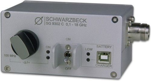
The comb-generator SG 9302 C produces a frequency spectrum consisting of lines with 100 MHz spacing up to 18 GHz. In combination with an antenna it can be used as an emission source for testing open area test sites, anechoic chambers or GTEM-cells. Single components like measuring receivers, spectrum analysers, cables and attenuators can be tested as well.
The operation is very simple and time saving because the spectrum lines are always present without any tuning procedure. The built in rechargeable battery makes it a versatile, simple and cost effective substitute for signal generators, which are still very expensive and therefore rare in the frequency range above 3,6 GHz.
The output level is relatively high for a comb-generator and the lines go well beyond 18 GHz. The limit for N- connectors is 18 GHz, so this limit is also given for the generator, though the spectrum is wider. A VCTCXO is used as frequency standard. This abbreviation stands for “Voltage Controlled Temperature Compensated Crystal Oscillator”.
The very good frequency stability of a crystal is made even better by a compensation circuit. Furthermore the nominal frequency can be tuned in a narrow range using a tuning voltage. This makes it possible to compensate small frequency differences between the comb-generator and a receiver. In open area test sites collisions with environmental signals can be avoided by tuning the frequency slightly.
Beginning of operation
Operation environment
The SG 9302 C is preferably used in buildings. Normally it is operated in laboratory rooms and chambers. While using on open area test sites, it must be protected from weather conditions, especially humidity.
Switching ON
The device is turned on with the pilot-style power-switch. Push the switch to the upper side. The green LED “On” indicates the proper charged battery. The red LED “Low Bat” means the battery is nearly empty. If the LED is dark even when the generator is turned on, the rechargeable battery is disconnected because of low voltage.
After charging the generator will be ready for operation. Turn the control on the right side of the front panel “-?f +“ in such a way that the white line on the knob points to "100 MHz". The combgenerator is now ready for measurement and can be connected, for example to an antenna.
Warning
Never connect the output of the combgenerator directly to the input of a receiver or spectrum-analyzer because there is potential danger for their input circuit. Always use a 10-dB-attenuator on the RF-input and don't switch off the automatic (default) 10 dB-attenuation of the receiver or spectrum-analyzer.
Practical measurement
Spectrum (Amplitude)
The spectrum delivered by the SG 9302 C covers the frequency range from 100 MHz to approximately 20 GHz. The upper limit of 18 GHz results from the fact, that N-connectors are specified up to 18 GHz only. We deliberately banned SMA from the front panel because it suffers more from mechanical stress due to its tiny dimensions.
The amplitude of the spectrum shows a continuous decay towards higher frequency with some minor "ripple".
In contrast to a typical signal generator, which can control the output level by rectifying and comparing it to a stable DC-voltage, the output spectrum of a comb-generator is unregulated. This means that the spectrum differs between units and also depends on other factors to a certain degree. It is good practise to prefer differential (compensation) measurement.
Stability of frequency
Using a temperature compensated crystal oscillator the frequency error is limited to ±1.5x10⁻⁶ (-20°C - +70°C). Even though this is good already, we have to take this point into consideration especially at higher frequencies.
At 18 GHz (worst case) the absolute maximum frequency error is ±27 kHz. The receiver may also have a comparable error which means that we have to face a potential higher frequency difference.
If a continuous frequency scan is made for a site attenuation measurement, this is no problem because the maximum of each spectrum line will be found anyway. In the case that only the expected frequencies are tuned, there are potential errors when the resolution bandwidth is not wide enough to compensate the tuning error. This is usually not the case because the resolution bandwidth is chosen relatively narrow to keep the noise down.
Intentional frequency tuning
Using the frequency fine tuning control " -?f + " the reference frequency can be shifted in a narrow range. The red LED illuminates when the fine tune is active to avoid unintentional frequency shifting which could result in wrong measurement.
The fixed position "100 MHz" is the standard position (LED dark). The intentional frequency tuning can be used to compensate for a frequency difference between the SG 9302 C and a receiver. However it must be considered that in contrast to a comb-generator, a receiver or spectrum–analyser has no simple relation between reference frequency and receiving frequency. A perfect tracking on one frequency may cause a severe offset somewhere else. Frequency tuning may also be helpful to avoid collisions with interfering signals for example in an open area test site.
Diagram and table
The measurement must be considered as typical. The absence of output level control leads to differences between units. Especially in the GHz-range cables and adapters may cause substantial loss. The measurement was made by connecting the output of the SG 9302 C to the RF-input of the spectrum-analyser via a qualified 10-dB-attenuator and an adapter N-connector / N-connector.
The table shows the voltage level of the spectrum lines in [dBµV]. To get the power level in [dBm] subtract 107 dB from the voltage level in [dBµV].
More information about the battery
The SG 9302 C is equipped with a 3.7 V Lithium cell. The battery voltage is indicated with a green LED for normal operation. If the red LED “Low Bat” is illuminated recharge is required.
A full battery charging period using the USB port takes around 5 hours. While recharging the yellow LED “Charge” is illuminated. The power-switch should be set to OFF during the recharging period. It is possible to measure during recharging. But disturbances generated by the charger could have an unwanted influence on the measurement.
A special circuit prevents the battery from being discharged completely. Whenever the voltage is too low for battery health or measurement precision, it will be automatically isolated from the load. When the SG 9302 C is switched ON and the red LED below is dark, this isolation has taken place. In this case the battery must be charged immediately. The second best advice is to switch OFF the SG 9302 C to avoid the (very low) idle current of the protection circuit.
| Specifications | |
| Connector female | N, 50 ? |
| Output voltage level typical | see Datasheet |
| Frequency error | +-1,5 x 10⁻⁶ (-20°C-+70°C) |
| Dimension | 105 x 80 x 130 mm |
| Typical operation time | 8 h |
| Power supply | 3.7 V, 2.6 Ah LiOn |
| Weight (incl. battery) | 430 g |


