Overview
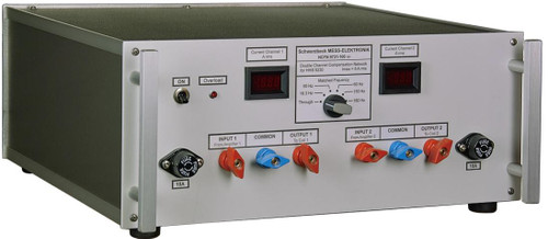
The primary function of the compensation network NFCN 9734 is to provide a serial compensation of the inductance of Helmholtz coils (e.g. the HHS 5206-16). Thus the currents needed to produce the desired field strength can be achieved using relatively low voltages.
An integrated shunt allows measuring the coilcurrent and serves as minimum load for the power amplifier.
The compensation network NFCN 9734 consists of a series circuit of a variable capacitor and a fuse. Its purpose is to compensate the inductance of the Helmholtz coils HHS 5206-16 at operating frequencies of about 200 Hz up to 200 kHz. If no compensation is necessary, the signal is looped through.
There are 23 different capacitors and a short available. They are connected between “Power Amplifier” and “Coil (to A)” utilizing relays.
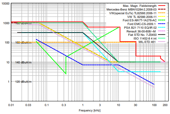
The following graph shows the maximum reachable magnetic field strength of the system (HHS 5206-16, LFPA 9733 and NFCN 9734) – in relation to common standards.

Max. magnetic fieldstrength of HHS 5206-16 with LFPA 9733 and NFCN 9734
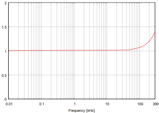
Internal 1 Ohm Shunt
The integrated 1 Ohm (800W) shunt allows measuring the coil-current and serves as minimum load for the power-amplifier. The internal fans are automatically enabled if the shunt becomes hot.
The shunt can be used stand-alone without the compensation network. But the cooling fans are only working when NFCN 9734 is turned on.
The following chart shows the total impedance of the shunt versus the frequency.
| Frequency, [kHz] | Impedance “1Ω”, [Ω] |
| 150 | 1.130 |
| 180 | 1.173 |
| 200 | 1.206 |
| 210 | 1.223 |
| 220 | 1.240 |
| 230 | 1.256 |
| 250 | 1.295 |
| 280 | 1.353 |

Hazard warning:
Attention: Life-endangering high voltages occur at the terminals of the coils and the NFCN 9734 during operation. If used in an inappropriate way this could lead to a life-threatening situation for the user!
Danger to life! High voltages!
The generator must be switched off every time wires are being connected or disconnected.
Important!
Switching capacitors is allowed without an applied signal level only. Otherwise the power amplifier could be damaged and the life expectancy of the relays will be decreased dramatically!
Currents between capacitors of different chargelevels can be extremely high. Occurring currents are limited by the loss resistance of the capacitors and the relay contacts only and can rise up to several hundreds of amperes. This can lead to welded relay contacts, especially at high capacitances within the lower frequency range.
Cooling
Please note that the air intake for cooling purposes is located on the sides of the amplifier and the warm air is exhausted at the back.
The amplifier must not be installed closer than 10 cm to a wall. It has to be installed in a way that the exhausted warm air cannot get into the housing again (thermal short). Pay attention to cooling especially when installing the amp into a 19” rack!
A 19’’-rack mount kit is available optionally.


