Overview
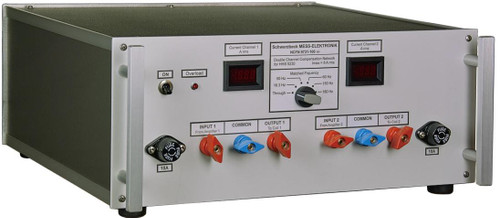
The compensation network NFCN 9732 85 kHz consists of a high current/ high voltage variable capacitor.
The compensation capacitor reduces the total impedance of the series circuitry consisting of the Helmholtz coil HHS 5206-8 and the NFCN 9732 85 kHz at the operating frequency band of 80-90 kHz. It allows continuous currents of up to 15 Arms at generator voltages of less than 40 Vrms.
You can choose from 11 different capacitance values with a rotary switch in 1 kHz steps from 80 kHz to 90 kHz. When using test frequencies that are between the given frequencies use a position that is closest to the needed frequency.
A capacitance of 15.7 nF is hard wired to the 4 mm safety laboratory connectors. The variable capacitor part gets added to the total capacitance value by using relays.
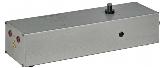
Fig. 2 View of the Connectors for the Capacitor
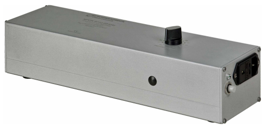
Fig. 3 Power Switch and IEC Connector
First steps with the overall system:
To set up the whole test system the following components are required:
- Helmholtz coil Schwarzbeck HHS 5206-8
- Compensation network Schwarzbeck NFCN 9732 85 kHz
- Power amplifier Schwarzbeck LFPA 9733
- Cable set
- Function generator
- Voltmeter
Setting up the system:
- Connect all components of the system according to Fig. 4.
- Connect the 3 m cable to terminal “A” and “C” of the Helmholtz coil. The short cable included within the scope of delivery connects terminals “B” and “D”.
- You can find the IEC mains connector and the voltage selection on the right side of the device. Set the voltage selector according to the local requirements. The device can be switched on using the power switch on the same side of the device and a LED indicates that the device is turned on. The working frequency can be set with the rotary switch on top of the device.
- The SHUNT 9571 has to be set to 1 ?. Therefore connect the shorting bar between terminals B1 and B2.
- Then connect all devices to mains.
- Set the voltmeter to measure AC voltage.
- Adjust the test frequency of your function generator and set it to “SIGNAL OFF”.
- Set the volume level of the amplifier to 50%.
- The coil factor of the HHS 5206-8 is 19.23 m-1. Thus if the field strength you aim for is 200 A/m you have to set the current to 10.4 A (200 / 19.23 = 10.4A).
Raise the output voltage of the function generator until the right current flows. Because the components heat up during operation the current has to be re-adjusted when necessary.
Important!
Switching capacitors is only allowed when no signal is connected to the NFCN. Otherwise the operational life span of the relays gets reduced dramatically.
Hazard warning:
Attention: During operation the voltages at HHS 5206-8 and at NFCN 9732 85 kHz will be much higher than at the amplifier output. When used inappropriate there will be danger to life!
Do not touch the terminals during operation. Switch off the complete system before touching any connections.
Only trained personnel may use this device.
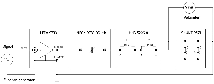
Fig.4. Measurement setup of the overall system
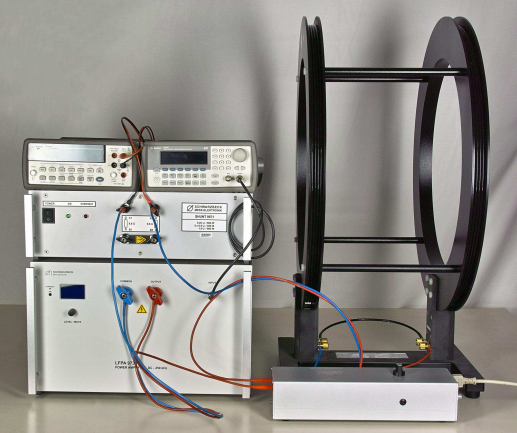
Fig. 5 Typical setup of the test system IMMSYS 85 kHz,
consisting of function generator, power amplifier LFPA 9733,
compensation network NFCN 9732 85 kHz,
Helmholtz coil HHS 5206-8, SHUNT 9571 and voltmeter.


