Overview
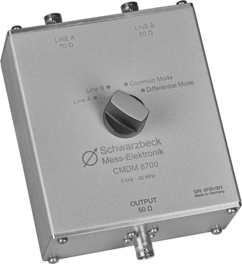
The measurement mode switch CMDM 8700 expands the measurement possibilities of two V-LISN to T- and Delta-LISNs for the profound analysis of interference emissions.
You can measure the signals in four different ways:
- “Line A”
- “Line B”
- “Common Mode”
- “Differential Mode”
If the mode switch is set to “Line A” or “Line B” the unsymmetrical signals of the inputs A or B will be measured directly. The line which is not used at the moment will be terminated with 50 Ω internally. (V-LISN)
If the switch is set to the position "Common Mode" the common asymmetrical components of both inputs will be measured. (T- , Delta-LISN)
If the switch is set to "Differential Mode" the CDMD 8700 extracts the symmetrical components (common mode voltage) and routes them to the measurement output. (Delta-LISN)
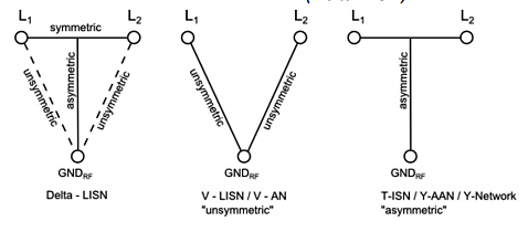
Fig. 1. LISN Topologies
To protect the measurement receiver from low frequency interferences (below 7 kHz) there is a built-in high pass filter at the output. Measurements using the different operation modes allow to find the source of interference easier and to take steps to eliminate them. As for instance to suppress conducted common mode interferences common-mode chokes are used and bypass capacitors are connected to ground. When differential mode interferences occur you need to connect capacitors between the lines.
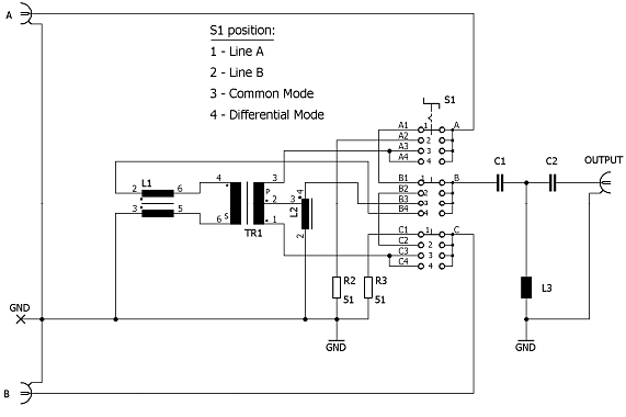
Fig. 2. Schematic circuit diagram of the CMDM 8700
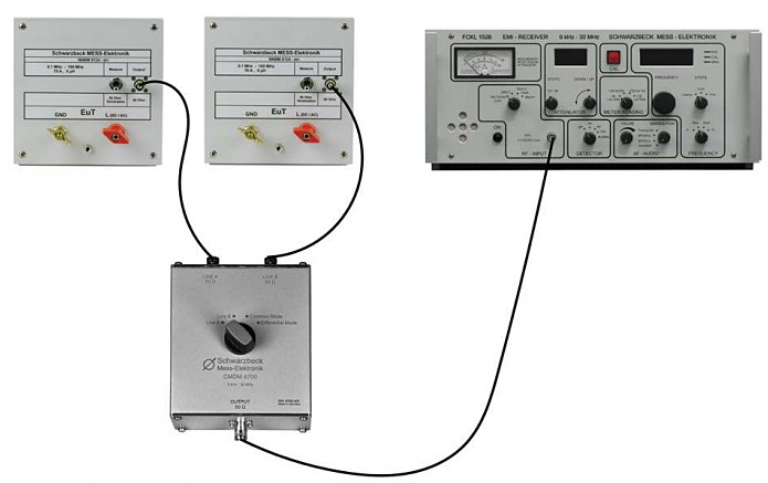
Fig. 3. Typical measurement Setup
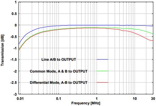
Fig. 4. Transmission of the inputs A and B
to OUTPUT using different modes
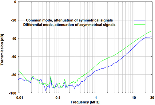
Fig. 5. Attenuation of symmetrical signals in common mode
and asymmetrical signals in differential mode
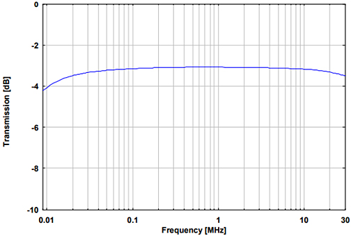
Fig. 6. Attenuation of unsymmetrical signals from A or B to OUTPUT in common mode.
The input that is not used is terminated with 50 Ω.
| Specifications | |
| Frequency range | 9 kHz – 30 MHz |
| Connectors | BNC |
| Impedance of Line A, Line B and output port | 50 Ω |
| Voltage division factor at the measuring port | (0 … - 2) dB |
| Material | Aluminium |
| Dimensions (housing W x H x D) | 105 x 49 x 120 mm |
| Weight | 490 g |

