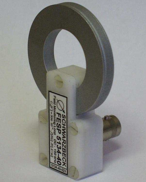
Overview
The purpose of this document is to provide the safety instructions that are required to operate the radiating loop FESP 5132. Special care should be taken by people with magnetic-field-sensitive implants (e.g. pacemakers). This document reports the simulation results that have been performed using FEMM (Finite Element Method Magnetic).
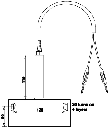
A model of the radiating loop has been developed (Fig. 1) and the results are presented in terms of the magnetic field intensity as a function of the distance (Fig. 2). The magnitude of the flux intensity (Fig. 3 & 4) and the magnitude of field strength (Fig. 5 & 6) are presented as a function of the increasing distance from the center of the radiating loop and for different currents. The intentional operating direction of the coil has been assigned with x and the radial direction with r.
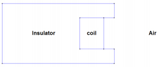
Fig. 1: Geometrical model of the FESP 5132 radiating loop in FEMM.
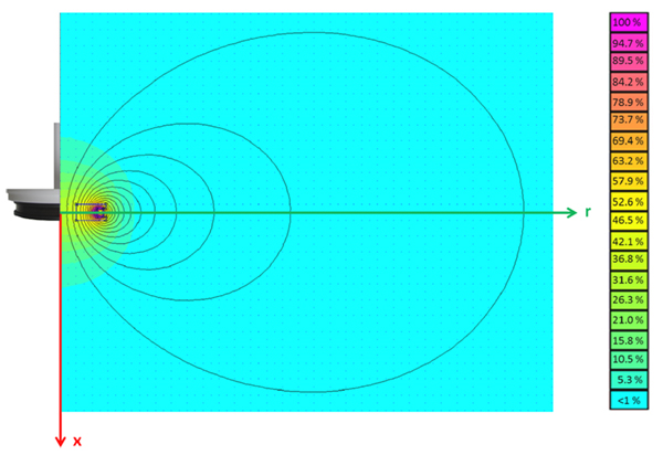
Fig. 2: The magnetic field intensity in a sectional plane of the FESP 5132.
The coil current was set to 1 Ampere. Results are shown in percentiles of the
maximum field strength that is produced in the inner region of the coil.
A picture of the FESP 5132 is overlapped and the two axis x and r
are highlighted in green and red, respectively.
Along these x and r axis the magnetic field flux has been analyzed.
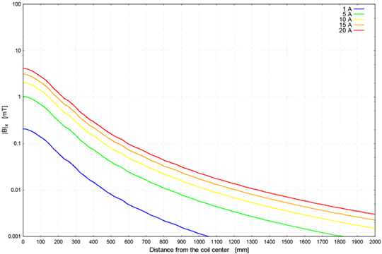
Fig. 3: The magnitude of the magnetic flux density measured
along the x-axis as a function of the distance from
the coil center and the current through the coils.
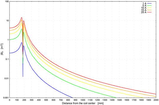
Fig. 4: The magnitude of the magnetic flux density measured
along the r-axis as a function of the distance from the
coil center and the current through the coils.
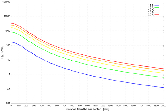
Fig. 5: The magnitude of the magnetic field strength measured
along the x-axis as a function of the distance from the
coil center and the current through the coils.
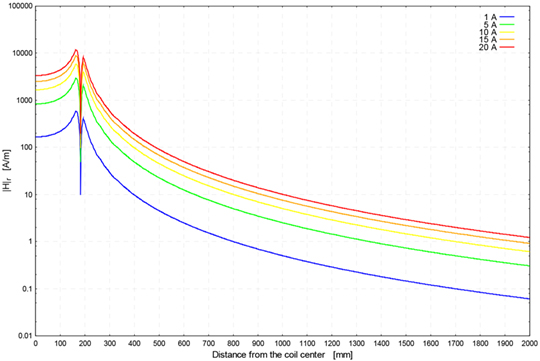
Fig. 6: The magnitude of the magnetic field strength measured
along the r-axis as a function of the distance from the
coil center and the current through the coils.
Application
The magnetic, handheld coil FESP 5132 was designed to generate defined magnetic fieldstrength in the audio frequency range up to 100 kHz. The main application is immunity testing against magnetic fields according to EN 55103 and MIL-STD-461 E. Depending on the current source characteristics magnetic fields up to 1500 A/m can be generated for a short time.
The generated magnetic fieldstrength is proportional to the coil current. A distance ring allows a precise spacing of 50 mm between coil and EUT surface. Other distance rings can be used to scale the current-fieldstrength ratio. The highest fieldstrength levels can be achieved using the shortest ring.
There are further rings available on request in order to provide a certain scaling between coil current and magnetic fieldstrength (e.g. 1 Amp coil current = 100 Amp/m fieldstrength). Economic current sources in the frequency range from 10 Hz up to 100 kHz are Audio amplifiers, which are available in nearly all power ratings.
The main part of the generated magnetic field is perpendicular (orthogonal) to the EuT-surface, i.e. in the same direction as the 22 mm handle. The achievable accuracy for generating defined magnetic fields depends on the accuracy of current measurements. In some cases (with moderate fieldstrength requirements) it may be advisable to use a well known series resistor and measure the voltage across this resistor.
The resistor can be scaled in a way to obtain a convenient voltage reading which corresponds to the generated magnetic field. The larger the series resistor compared to the inductance, the more frequency independant characteristics will be achieved (but the efficiency of fieldstrength reduces).
Application as magnetic field probe
The FESP 5132 can also be used to measure existing magnetic fields. The open circuit output voltage is directly proportional to the magnetic fieldstrength (at fixed frequency) or directly proportional to frequency (at constant magnetic fieldstrength). The characteristic is shown in the graph below for some constant magnetic fieldstrength values.
It is advisable to use high impedant measuring equipment for the output voltage of FESP 5132. If 50 Ω measuring equipment is used the source impedance of the FESP 5132 must be considered at higher frequencies arbove 30 kHz (50 Ω at 100 kHz, 100 Ω at 200 kHz). The following diagram shows the open circuit voltage measured with a high impedant voltmeter and the voltage across 50 Ω.
| Specifications | |
| Number of turns | 20 |
| Wire diameter | 2 mm Cu (AWG 12) |
| Maximum Coil Current | 20 A, 5 min. |
| Nominal Coil Current | 10 A continuous |
| Maximum Magnetic Field Strength | 1500 A/m, 5 min. |
| Nominal Magnetic Field Strength | 750 A/m continuous |
| Magnetic Fieldstrength, 1 A Coil Current (with 50 mm distance ring) | 75.56 A/m (95 µT) |
| Current required for 1 A/m (with 50 mm distance ring) | 13.23 mA |
| Medium coil diameter | 120 mm |
| Spacing coil center to measurement plane | 50 mm |
| Mechanical Dimensions | 0.16 m x 0.25 (0.3) m |
| Terminals | banana jacks: 4 mm |
| Usable Frequency Range | 0 - 150 kHz |
| Inductance | 80 µH |
| Resistance | 0.1 Ω |
| Weight | 1.2 kg |


