Overview
The EMC Shop is an ISO 17025 accredited calibration company with the Schwarzbeck TEMZ 5238 Symmetrical Stripline in stock available for sale or rental. Repair and refurbishment services available as well. Contact us now for application support.
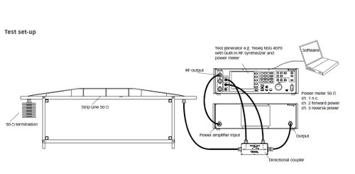
Open, nearly symmetrical stripline acc. to CISPR 20 for immunity testing and calibration purposes. The stripline is equipped with a 4:1 balun for impedance matching to the 50 Wsystem and to achieve symmetry. The termination of the stripline is achieved with a symmetrical 200 W load.
The symmetrical stripline complies to the requirements of CISPR 20. In order to achieve a smooth fieldstrength characteristic throughout the length, the stripline is terminated with 50 W, transformed via a 4:1 balun. Alternatively a symmetrical 200 W termination can be used. The stripline can be used to create TEM-waves up to max. 53 MHz.

The fieldstrength distribution at TEM-mode operation inside the stripline is very homogenous. The stripline can also be used above 53 MHz, in this case higher modes do exist, which offer a location dependant fieldstrength characteristics. In contrast to the TEM-mode, where the fieldstrength is small at the edge of the stripline and increases towards the center, the higher modes show opposite characteristics: the fieldstrength is small at the center of the stripline and rises to maximum values at the edge of the strip conductor.
Further, the direction of polarisation changes at some areas during multi mode operation. At TEM-mode operation there are only small losses caused by radiation and dielectrical losses of the plastic support rods. Less than 1% of the incident power is reflected back into the source, caused by minimized impedance mismatch. The dielectric and radiation losses at TEM operation frequencies are as follows: |S21| = 0.5 dB, losses: 11%, |S21| = 1.0 dB, losses: 21%. The losses increase for multi mode operation.
An ideal tool for monitoring the actual fieldstrength inside the stripline is the small active E-field antenna EFS 9218 and the small active loop antenna HFS 1546. For positioning of the EuT it is recommended to use (nearly) dielectric neutral material, e.g. foam or polystirene plastics. The suitability of the material can be checked as follows: the insertion loss of the empty cell is measured, then the material under test is placed in the cell and the insertion loss is measured again.
Minimum differences in attenuation of the empty and loaded cell indicate a suitable material. The equipment under test (EuT) should be placed in the center of the stripline.
It is recommended to record the EuT-position as exactly as possible in order to achieve a good reproducability of the tests.


