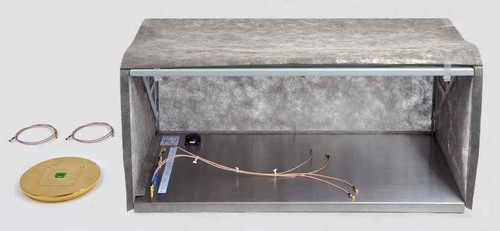
Overview
The E1 is a set of EMC tools used for EMI suppression in printed circuit boards during the development phase. The developer can use the E1 set to quickly identify the causes of burst and ESD interference. This allows the developer to design suitable measures to solve the causes of the interference. It can also be used to test the effectiveness of the measures taken. The E1 test set-up is small and fits easily on a developer's desk. The E1 set user manual describes EMC mechanisms and provides detailed descriptions of basic measuring strategies for interference suppression in printed circuit boards. The E1 set includes a generator to generate burst and ESD disturbances.
Scope of delivery
1x SGZ 21, Burst Generator
1x S21, Optical Sensor (10 Mbps)
1x BS 02, Magnetic Field Source
1x BS 04DB, Magnetic Field Source
1x BS 05D, Magnetic Field Source
1x BS 05DU, Magnetic Field Source
1x ES 00, E-Field Source
1x ES 01, E-Field Source
1x ES 02, E-Field Source
1x ES 05D, E-Field Source
1x ES 08D, E-Field Source
1x MS 02, Magnetic Field Probe
1x E1 acc, Accessories
1x NT FRI EU, Power Supply Unit
1x E1 case, System Case
1x E1 m, E1 Set User Manual
| Technical parameters | |
| S21 Optical Sensor | |
| Transmission range | DC...10 Mbps |
| Optical fibre connector | 2.2 mm Ø |
| Supply voltage | (3-5) V |
| Current input | 10 mA |
| SGZ 21 Burst Generator | |
| Pulse parameter | |
| Rise time | ca. 2 ns |
| Tail time | ca. 10 ns |
| Peak values | ca. 0...1500 V |
| Optical input | |
| Optical fiber | 2.2 mm |
| Max. frequency | 5 MHz |
| Min. pulse width | 100 ns |
| Supply voltage | 12 V / 200 mA |
| Sizes (L x W x H) | (154 x 100 x 62) mm |
| Measuring principles |  |
E1 Immunity Development System
The E1 immunity development system is an advanced tool for the electronics developer to examine the immunity of modules to pulsed interference (burst/ESD) in experiments. The system allows him to analyse the interference immunity in the confined space of a module. The selective injection of disturbance current into individual sections (disturbance current paths) and application of pulsed electric (E fields) or magnetic (H fields) fields to selected areas of the module's surface are decisive for the localisation of weak points. While pulsed disturbances are applied to the device under test, the signals can be monitored simultaneously via optical fibre without interaction.
The E1 immunity development system has been specially designed for the development process. It helps the developer suppress interference in devices/modules or further harden them since it allows him to clarify the immediate causes of immunity problems and test the effects of counter-measures directly.
The E1 immunity development system cannot be used for standard compliance tests. Testing a module's immunity on the basis of the IEC 61000-4-4 and IEC 61000-4-2 standards, however, is an ideal starting point for examining the device under test with the E1. The disturbances generated by the standard burst generator in accordance with the standard are injected into the supply lines of the device under test and flow back to the generator via ground. The paths on which the pulse-shaped disturbances flow through the device module are not known. An unknown percentage of these disturbances encounters an unknown victim in the device and generates a functional fault. This weak point can usually be pinpointed to a few square centimetres of a module but can only be localised with difficulty in a standard compliance test. The developer does not yet know if and where the disturbance current with its associated magnetic field induces a voltage pulse in a conductor loop or couples electric field capacitively to sensitive lines.
Exact information about the fault pattern that has occurred is the decisive result of a failed compliance test. But the fault pattern does not reveal precisely where the weak point of the device under test lies. A test in accordance with the standard should thus initially be performed to determine the immunity of the device under test so as to identify the fault pattern. The developer can then use the E1 at his workplace to analyse the causes of the immunity problems, where the functional faults shown in the fault pattern provide a certain orientation for interference suppression. The immunity development system allows the developer to verify the effectiveness of EMC modifications carried out in the interference suppression process immediately and thus to achieve a significant reduction in the development time and development costs.
E1 Components
The E1 immunity development system comprises a SGZ 21 pulse density / burst generator, an S21 optical sensor, an MS 02 magnetic field probe with optical fibre output, magnetic and electric field sources and numerous accessories.

E1 hardware scope of delivery


