Overview
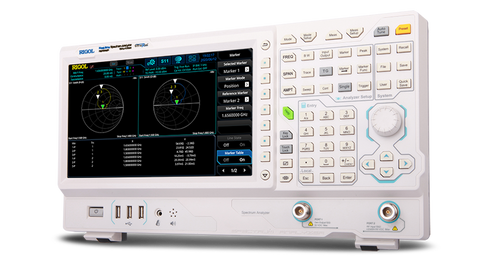
The Rigol DSA710 is a compact and light weight Spectrum Analyzer with premium performance for portable applications. The use of digital IF (intermediate frequency) technology guarantees reliability and performance to meet the most demanding RF applications. The very large display (20.3 cm / 8") of the Rigol DSA710 Spectrum Analyzer provides a resolution of 800x480 pixels allowing a very good overview of all its comfortable functions like Auto Tune, Auto Range, Auto Scale and Auto Couple. These functions enable the analyzer to acquire signals and match parameters automatically, compared to the manual process necessary with a traditional analyzer. The Rigol Spectrum Analyzers have a sophisticated and easy to use user interface offering multiple functions for all tasks. The menu navigation is very intuitive and all functions and parameters are easy to locate thanks to the graphical interface.
Benefits of Rigol's all Digital IF Design
- High precision amplitude readings: this technology almost eliminates the errors generated by filter switching, reference level uncertainty, scale distortion, as well as errors produced in the process of switching between logarithmic and linear display of amplitude when using a traditional analog IF design.
- Higher reliability: compared with traditional analog designs, the digital IF greatly reduces the complexity of the hardware, the system instability caused by channel aging, and the temperature sensitivity that can contribute to parts failure.
- The ability to measure smaller signals: on the basis of this technology, the IF filter enables smaller bandwidth settings, which greatly reduce the displayed average noise level.
- The ability to distinguish between small signals by frequency: using the IF filter with the smallest bandwidth setting, it is possible to make out signals with a frequency difference of only 100 Hz.
- High measurement speed: the use of digital IF technology improves the bandwidth precision and selectivity of the filter, minimizing the scanning time and improving the speed of the measurement.
Key Functions
SPECIFICATIONS | ||
Specifications are valid under the following conditions: the instrument is within the calibration period, is stored for at least two hours at 0°C to 50 °C temperature, and is warmed up for 40 minutes. Unless otherwise noted, the specifications in this manual include the measurement uncertainty. Typical (typ.): characteristic performance, which 80 percent of the measurement results will meet at room temperature (approximately 25°C ). This data is not warranted and does not include the measurement uncertainty. Nominal (nom.): the expected mean or average performance or a designed attribute (such as the 50O connector). This data is not warranted and is measured at room temperature (approximately 25°C ). Measured (meas.): an attribute measured during the design phase which can be compared to the expected performance, such as the amplitude drift variation with time. This data is not warranted and is measured at room temperature (approximately 25°C ). NOTE: All charts in this manual are the measurement results of multiple instruments at room temperature unless otherwise noted. The specifications (except the TG specifications) listed in this manual are those when the tracking generator is off. | ||
DSA705 | DSA710 | |
Frequency | ||
Frequency range | 100 kHz to 500 MHz | 100 kHz to 1 GHz |
Frequency resolution | 1 Hz | |
Internal Reference Frequency | ||
Reference frequency | 10 MHz | |
Accuracy | ±[ (time since last calibration × aging rate) + temperature stability + calibration accuracy] | |
Initial calibration accuracy | <1 ppm | |
Temperature stability | 0? to 50? , reference to 25? | |
<2 ppm | ||
Aging rate | <2 ppm/year | |
Frequency Readout Accuracy | ||
Marker resolution | span/ (number of sweep points - 1) | |
Marker uncertainty | ±(frequency indication × reference frequency accuracy + 1% × span + 10% × resolution bandwidth + marker resolution) | |
Frequency Counter | ||
Resolution | 1 Hz, 10 Hz, 100 Hz, 1 kHz, 10 kHz, 100 kHz | |
Uncertainty | ±(frequency indication × reference frequency accuracy + counter resolution) | |
Frequency Span | ||
Range | 0 Hz, 100 Hz to maximum frequency of instrument | |
Uncertainty | ±span/ (number of sweep points - 1) | |
SSB Phase Noise | ||
20? to 30? , fc = 500 MHz | 20? to 30? , fc = 1 GHz | |
Carrier offset | <-80 dBc/Hz | <-100 dBc/Hz (typ.) |
Residual FM | ||
20? to 30? , RBW = VBW = 1 kHz | ||
Residual FM | <50 Hz (nom.) | |
Bandwidths | ||
Set "Auto SWT" to "Accy" | ||
Resolution bandwidth (-3 dB) | 100 Hz to 1 MHz, in 1-3-10 sequence | |
RBW uncertainty | <5% (nom.) | |
Resolution filter shape factor (60 dB : 3 dB) | <5 (nom.) | |
Video bandwidth (-3 dB) | 1 Hz to 3 MHz, in 1-3-10 sequence | |
Resolution bandwidth (-6 dB) (EMI-DSA800 option) | 200 Hz, 9 kHz, 120 kHz | |
Amplitude | ||
Measurement Range | fc ≥ 10 MHz | |
DANL to +20 dBm | ||
Maximum Input Level | ||
DC voltage | 50 V | |
CW RF power | attenuation = 30 dB | |
+20 dBm (100 mW) | ||
Max. damage level[1] | +30 dBm (1 W) | |
NOTE: [1] When fc ≥ 10 MHz, input level > +25 dBm and PA is Off, the protection switch will be on. | ||
Displayed Average Noise Level (DANL) | ||
Frequency | attenuation = 0 dB, RBW = VBW = 100 Hz, sample detector, trace average ≥ 50, 20? to 30? , input impendence = 50 Ω | |
PA off | 100 kHz to 1 MHz <-90 dBm, <-110 dBm (typ.) | |
1 MHz to 500 MHz <-100 dBm, <-110 dBm (typ.) | ||
500 MHz to 1 GHz <-100 dBm, <-110 dBm (typ.) | ||
PA on | 100 kHz to 1 MHz <-110 dBm, <-130 dBm (typ.) | |
1 MHz to 500 MHz <-120 dBm, <-130 dBm (typ.) | ||
500 MHz to 1 GHz <-120 dBm, <-130 dBm (typ.) | ||
Level Display | ||
Logarithmic level axis | 1 dB to 200 dB | |
Linear level axis | 0 to reference level | |
Number of display points | 601 | |
Number of traces | 3 + math trace | |
Trace detectors | normal, positive-peak, negative-peak, sample, RMS, voltage average quasi-peak (with EMI-DSA800 option) | |
Trace functions | clear write, max hold, min hold, average, view, blank | |
Units of level axis | dBm, dBmV, dBμV, nV, μV, mV, V, nW, μW, mW, W | |
Frequency Response | ||
Frequency response | fc ≥ 100 kHz, attenuation = 10 dB, relative to 50 MHz, 20? to 30? | |
PA off | 100 kHz to 500 MHz <0.7 dB | |
500 MHz to 1 GHz <0.7 dB | ||
PA on | 100 kHz to 500 MHz <1.0 dB | |
500 MHz to 1 GHz <1.0 dB | ||
Input Attenuation Switching Uncertainty | ||
Setting range | 0 dB to 30 dB, in 1 dB step | |
Switching uncertainty | fc = 50 MHz, relative to 10 dB, 20? to 30? | |
<0.5 dB | ||
Absolute Amplitude Uncertainty | ||
Uncertainty | fc = 50 MHz, peak detector, preamplifier off, attenuation = 10 dB, input signal level = -10dBm, 20? to 30? | |
<0.4 dB | ||
RBW Switching Uncertainty | ||
Uncertainty | relative to 1 kHz RBW | |
<0.1 dB | ||
Reference Level | ||
Range | -100 dBm to +20 dBm, in 1 dB step | |
Resolution | log scale 0.01 dB | |
linear scale 4 digits | ||
Preamplifier | ||
Gain | 100 kHz to 500 MHz - 20 dB (nom.) | |
500 MHz to 1 GHz - 20 dB (nom.) | ||
Level Measurement Uncertaint | 95% confidence level, S/N > 20 dB, RBW = VBW = 1 kHz, preamplifier of f, attenuation = 10 dB, -50 dBm < input level ≤ 0 dBm, fc > 10 MHz, 20? to 30? | |
Level measurement uncertainty | <1.5 dB (nom.) | |
RF Input VSWR | attenuation ≥ 10 dB | |
VSWR | 300 kHz to 500 MHz <1.5 (nom.) | |
500 MHz to 1 GHz <1.5 (nom.) | ||
Distortion | ||
Second Harmonic Intercept | ||
Second harmonic intercept (SHI) | fc ≥ 50 MHz, input signal level = -20 dBm, attenuation = 10 dB | |
+40 dBm | ||
Third-order Intercept | ||
Third-order intercept (TOI) | fc ≥ 50 MHz, two -20 dBm tones at input mixer spaced by 200 kHz, attenuation = 10 dB | |
+10 dBm | ||
1dB Gain Compression | ||
1dB compression of input mixer (P1dB) | fc ≥ 50 MHz, attenuation = 0 dB | |
>0 dBm | ||
Spurious Response | ||
Spurious response, inherent | input terminated 50 Ω, attenuation = 0 dB, 20? to 30? | |
<-88dBm (typ.) | ||
Intermediate frequency | <-60 dBc | |
System related sidebands | referenced to local oscillators, referenced to A/D conversion, referenced to subharmonic of first LO, referenced to harmonic of first LO | |
<-60 dBc | ||
Input related spurious | mixer level = -30 dBm | |
<-60 dBc | ||
Sweep | ||
Sweep time | span ≥ 100 Hz 10 ms to 500 s | span ≥ 100 Hz 10 ms to 1000 s |
zero span 20 μs to 500 s | zero span 20 μs to 1000 s | |
Sweep time uncertainty | span ≥ 100 Hz 5% (nom.) | |
zero span (sweep time setting value > 1 ms) 5% (nom.) | ||
Sweep mode | continuous, single | |
Trigger | ||
Trigger source | free run, video, external | |
External trigger level | 5 V TTL level | |
SSC-DSA (Option) | ||
Signal Seamless Capture (SSC) | ||
Measurement bandwidth | 202 kHz | |
Measurement speed | 650 spectrums/s | |
Input /Output | ||
Front Panel Connectoc | ||
RF input | impedance 50 Ω (nom.) | |
connector N female | ||
Internal/ External Reference | ||
Internal reference | frequency 10 MHz | |
output level +3 dBm to +10 dBm, +8 dBm (typ.) | ||
impedance 50 Ω (nom.) | ||
connector BNC female | ||
External reference | frequency 10 MHz ± 5 ppm | |
input level 0 dBm to +10 dBm | ||
impedance 50 Ω (nom.) | ||
connector BNC female | ||
External trigger input | impedance 1 kΩ (nom.) | |
connector BNC female | ||
Communication Interface | ||
USB host | connector A plug | |
protocol version2.0 | ||
USB device | connector B plug | |
protocol version2.0 | ||
LAN | LXI core 2011 device 10/100Base, RJ-45 | |
IEC/IEEE (GPIB) bus (USB-GPIB option) | IEEE488.2 | |
General Specifications | ||
Display | ||
Type | TFT LCD | |
Resolution | 800 x 480 pixels | |
Size | 8 inch | |
Colors | 64k | |
Printer Supported | ||
Protocol | PictBridge | |
Mass memory | flash disk (internal), USB storage device (not supplied) | |
Power Supply | ||
Input voltage range, AC | 100 V to 240 V (nom.) | |
AC supply frequency | 45 Hz to 440 Hz | |
Power consumption | 35 W (typ.), max. 50 W with all options | |
Environmental | ||
Temperature | operating temperature range 0° to 50° | |
storage temperature range -20° to 70° | ||
Humidity | 0° to 30° ≤ 95% rel. humidity | |
30° to 40° ≤ 75% rel. humidity | ||
Electromagnetic Compatibility and Safety | ||
EMC | in line with EN61326-1:2006 | |
IEC 61000-4-2:2001 | ±4.0 kV (contact discharge), ±4.0 kV (air discharge) | |
IEC 61000-4-3:2002 | 3 V/m (80 MHz to 1 GHz), 3 V/m (1.4 GHz to 2 GHz), 1 V/m (2.0 GHz to 2.7 GHz) | |
IEC 61000-4-4:2004 | 1 kV power lines | |
IEC 61000-4-5:2001 | 0.5 kV (phase to neutral), 0.5 kV (phase to PE), 1 kV (neutral to PE) | |
IEC 61000-4-6:2003 | 3 V, 0.15 to 80 MHz | |
IEC 61000-4-11:2004 | voltage dip: 0% UT during half cycle, 0% UT during 1 cycle, 70% UT during 25 cycles short interruption: 0% UT during 250 cycles | |
Electrical safety | in line with UL 61010-1:2012, CAN/CSA-C22.2 No. 61010-1-12, EN 61010-1:2010 | |
Dimensions | ||
(W x H x D) | 361.6 mm × 178.8 mm × 128 mm (14.2 in × 7.0 in × 5.0 in) | |
WeightStandard | 4.25 kg (9.4 lb) | |
Recommended calibration interval | 1 year |