Overview
The well known H-Field-Probes of the FMZB Series and the direct reading HMDA 1545 cover the frequency range 9 kHz - 30 MHz (80 MHz).
Using a smaller loop and a new loop amplifier with ten times faster transistors, the upper frequency limit was extended to 400 MHz.
So this probe permits the frequency selective measurement of the very low limits for medical implants.
Schwarzbeck HFS 1546 Application:
Typical application is frequency selective HField-Measurement outside and inside of buildings and rooms using test receivers or spectrum analysers.
The wide frequency and dynamic range covers the limits of human protection beginning at approximately 4.5 MHz as well as the very low limits for medical implants (heart pace-maker).
Field sources are AM and FM radio- and TVstations.
Furthermore there is a variety of military and civilian radio services, not to forget cb- and amateur radio.
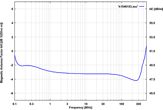
The antenna (conversion) factor is constant over nearly the complete frequency range giving a very natural field-strength image when spectrum-analysers are in use.
In order to eliminate power supply problems and stray coupling, NiMH rechargeable batteries are built in the mounting tube. The state of the battery is monitored by two LEDs. After more than ten hours of continuous operation, charging with the automatic charger takes about 2-4 hours.
Schwarzbeck HFS 1546 Indication equipment
Only a very sensitive measuring receiver can utilise the high sensitivity of the probe.
Common spectrum-analysers usually don't provide sufficient sensitivity. There is a low noise preamplifier available to solve the problem. Broad-band measurement of high field-strength can also be made with other equipment.
Care has to be taken to ensure that this equipment has a 50-Ω- input. A BNC- or other coaxial input connector is no guaranty for that.
Oscilloscopes with a BNC-input connector usually have an extremely high input impedance consisting of some MΩ in parallel to some pF. Some models have a switch to put a 50-Ω−termination in parallel. The situation is more or less the same considering r.-f.-millivolt-meters. Mismatch may be tolerated if only signal characteristics are monitored. For correct measuring a 50-Ω−termination is a must.
Schwarzbeck HFS 1546 Measurement
The probe converts magnetic field strength into a voltage (across 50 Ω), which is indicated by a measuring receiver, spectrum analyser or r.-f.- millivolt meter. The field-strength can be calculated using the antenna factor (conversion factor, transducer factor) of the probe. This factor is constant over the wide centre frequency range with some changes at the edges. The main antenna factor is -4 dB/Ωm.
A measuring receiver or spectrum analyser with a 50-Ω-input and dBµVreading is used for measuring. Reading in dBµV is very common in the emc-field and available on almost every receiver, using 0 dBµV acc. to 1 µV
The voltage level on a certain frequency (f. e. an am transmitter on 1 MHz) is measured. The antenna factor of -4.0 dB is added (4.0 dB subtracted) to the voltage level reading. The result is the magnetic field-strengthlevel in dBµA/m.
Schwarzbeck HFS 1546 Measuring high field-strength
The linear range of the probe ends at 105 dBµA/m acc. to 178 mA/m. Saturation begins "soft" and depends on the frequency.
Human protection limits are covered beginning at 4.5 MHz. Below this frequency the FMZB 1547/1548 is a good choice.
Higher field-strength levels lead to signal distortion and intermodulation products occur in the spectrum.
The same situation occurs with many weak signals. Whenever strange signals are recognised under high level conditions, increase the distance between probe and field source.
Intermodulation products then decrease faster than "real" signals.
Simple receivers and spectrum analysers with no or insufficient front-end-filtering may cause intermodulation while the probe is still linear.
In this case increase R.-F.-attenuation and decrease I.-F.-attenuation to reduce input saturation at the expense of noise.
Schwarzbeck HFS 1546 Measuring very low field strength
When a sensitive receiver or spectrum analyser is used, the noise of the probe is the limit for low field-strength measurement.Making the receiver bandwidth smaller will reduce noise indication.
Under the condition that the signal to measure is a narrow-band-signal, smaller receiver bandwidth will give better signal to noise ratio.
Choosing the average detector may reduce noise even more. There will be improvements for narrow band signals (cw) without modulation, but not for broad band signals and pulse spectrum. The following table shows the noise of the probe.
Measurement was made with the emireceivers FCKL 1528 and FCVU 1534. The bandwidths are standard emibandwidths.
Schwarzbeck HFS 1546 First steps with the probe
After connecting the probe to the receiver or spectrum analyser signals will appear. Broadcast transmitters in the AM-range can be easily monitored even in buildings and rooms.
This is also the case with FM-radio and TV. Because of the fact that the probe is directional, the maximum will be found by turning.
In office rooms emission is dominated by PCs, monitors and data networks. Industrial environment shows high fieldstrength on ISM-frequencies (Industrial, Scientific, Medical).
Even some receivers or spectrum analysers radiate electric field strength, which can be monitored with the probe.
Schwarzbeck HFS 1546 Battery
The probe contains 6 NiMH-cells with 1.2 V/1000 mAh each resulting in a voltage of 7.2 V (nom.).
The batteries are built in the antenna tube and completely shielded. Any stray coupling or other effects from outside are impossible.
The 10 hours of operation time is very conservative considering the current consumption of only 30 mA. Under these circumstances the reserve indication can occur very much on the safe side, providing sufficient time to complete the measurement. Furthermore the operation time will still be available after ageing.
Batteries of this kind have a very low resistance. After a short current they will heat up in seconds. Burning out of the insulating material between the cells leads to permanent inner short circuit with even more heat.
The battery is protected by a thermal switch and a fuse. But once a short circuit between cells is established, switch and fuse cannot prevent severe damage to the probe.
For this reason never open the probe or charge it with inappropriate charging equipment.
Avoid short circuits to the charging connector.
A SMA-connector is used for charging, which seems to be quite strange at the first view. The reason is that the SMAconnector is small and has good stability. The disadvantage is the common link between SMA and R.F.-equipment, which is not the case here. So never connect any other equipment to the charging connector or the charger! The optional charger ACS 410 (Ansmann) is a good choice because of the intelligent charging. The antenna tube may warm up while charging. This is normal.
Charging Connector:
Inner conductor: PLUS
Outer conductor: MINUS (MASSE)
| Schwarzbeck HFS 1546 Specifications | |
| Active H-Field-Probe with electrically shielded Loop | |
| Frequency range | 150 kHz - 400 MHz |
| Connector female | 50 Ω N |
| Mounting tube | 22 mm |
| Loop diameter | D =50 mm |
| Loop tube thickness | 6 mm |
| Total Length | LR=195 mm LH=610 mm |
| Antenna Conversion Factor KH (typ) | -4,0 dB(1/Ωm) |
| Maximum Field-Strength | 105 dBµA/m |
| Mimimum Field-Strength typ. | -13,5 dBµA/m; 0,2 µA/m (FE=30 MHz, ▲F=9 kHz, Avg.-Det.) |
| Inversion Symmetry | typ. < 1 dB 100 kHz - 250 MHz |
| Operation Time | >10 h |
| Power Supply | 7,2 V, 1000 mAh NiMH |
| Weight (incl. batteries) | 890 g |
Active Magnetic Field Probe with Electrically Shielded Loop


