Overview
The EMC Shop is an ISO 17025 accredited calibration company with the Schwarzbeck HFRA 5154 in stock available for sale or rental. Repair and refurbishment services available as well. Contact us now for application support.
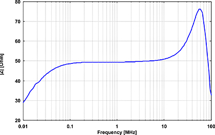
The transmit loop antenna HFRA 5154 was designed to generate well defined magnetic fields with moderate fieldstrength levels (< 0.1 A/m) in the frequency range 100 kHz to 30 MHz. With slightly reduced performance the loop can be used in the frequency range up to 50 MHz. The loop, consiting of two turns, is shielded against E-fields. The nickelplated brass housing contains a toroid transformer (current transformation ratio 2:1) and the termination resistor (max. 0.5 W). The transformer allows very good matching to the widely used 50 W measurement equipment and an extremely flat frequency response over the entire frequency range. The loop can mounted at its female large camera thread.
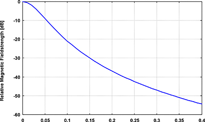
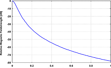
The generated magnetic field is proportional to the loop current. A tabular indicates the fieldstrength values in A/m and dBµA/m to be expected with the maximum permissible current of 100 mA. Additionally the relative decrease of magnetic fieldstrength referred to the center of the loop antenna can be found. Lower magnetic fieldstrengths can be achieved by scaling the current to the respective value. With a feed current of 10 mA instead of 100 mA the tabular values decrease by a factor of 10, which corresponds to a reduction by 20 dB in logarithmic measure. All specified magnetic fieldstrengths refer to the component which is perpendicular to the loop-plane.
Application:
Both female BNC-connectors are directly wired with each other. One of them can be used to feed the loop, the other can be used to monitor the voltage with a voltmeter (high impedance). The measurement distance to apply for the calibration of RX-loops depends on the RX-loop dimensions. For large loop antennas a higher calibration distance is required in order to obtain a uniform field distribution over the complete loop area. The shorter the distance, the smaller the uniform area and the size of antennas to be calibrated. The following table indicates the recommended minimum calibration distances, depending on the loop diameter of the loop under calibration and the wanted field uniformity.
| Specifications | |
| Frequency Range | 0.1-30 MHz |
| Impedance | 50 Ω |
| VSWR | < 1.3 |
| Number of turns | 2 |
| Current transformation ratio | 2:1 |
| Loop diameter | 100 mm |
| Maximum Current | 100 mA / 100 dBµA |
| Maximum Voltage | 5 V / 134 dBµV |
| Maximum Power | 0.5 W / +27 dBm |
| Mechanical Dimensions | 160 x 112 x 62 mm |
| Terminals | BNC |
| Mount | 3/8" |
| Weight | 250 g |
Impedance at BNC-Connector |
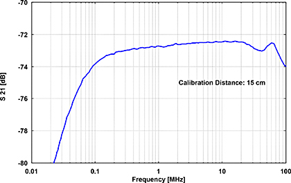
Attenuation between HFRA 5154 + HFRAE 5161 |
Distance to Center [m] |
Distance to Center [m] |


