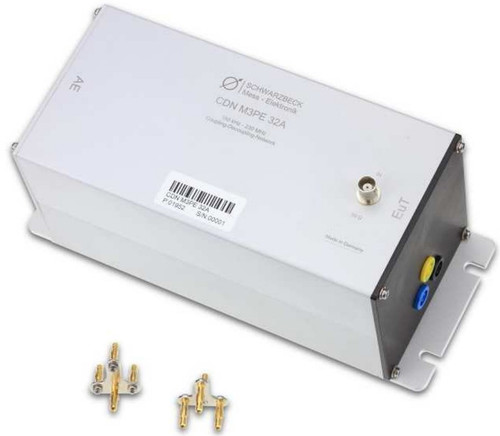
Overview
The CDN M3PE 16A is part of the coupling decoupling network series for conducted common mode immunity testing according to IEC 61000-4-6. The CDN M3PE 16A is compliant to IEC 61000-4-6 Annex D.2 and is suitable for immunity testing on unscreened a.c. and d.c. power supply lines (mains lines).
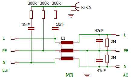
The CDN M3PE 16A is intended to inject common mode disturbance signals to power supply or mains lines (unscreened) in the frequency range from 150 kHz to 230 MHz. The circuitry is shown in Fig. 5.
All CDNs comply to the requirements of IEC 61000-4-6. Each CDN comes with individually measured data and a calibration certificate for the common mode impedance and the voltage division factor. Further typical data can be found in fig. 3 and fig. 4
A variety of calibration adapters and other accessories are available as option.
Important Note:
The optional shorting adapters must not be used if the CDN is connected to mains!
The capacitors at the AE-side are equipped with 2 M? discharging resistors.
Corresponding terminals are always located in opposite position and can be recognized by the terminal color. They can be used for any phase, except for PE! The PE-terminal with its yellow-green color is connected to the metal housing at the AE-side.
To improve the operational safety the mains voltage-carrying connections are carried out as security sockets. We recommend to use special 4 mm security plugs if you plan to design your own adapters. Those connectors can be purchased optionally.
Caution: The safety connectors come with a selflock to avoid unintentional connection interrupts. Removal of the connector requires therefore a full push in.
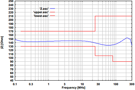 | 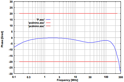 |
| Fig. 1: typ. EuT common mode impedance | Fig. 2: typ. phase EuT-Port, (common mode), informative |
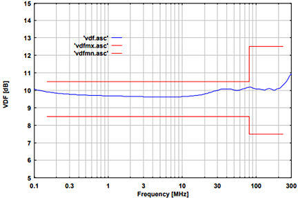 | 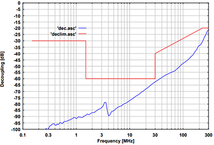 |
| Fig. 3: typ. voltage division factor RF-port to EuT-port | Fig. 4: typ. Isolation between AE and RF-Port, informative |
| Specifications | |
| Frequency range | 150 kHz … 230 MHz |
| Common mode impedance | 150 kHz – 24 MHz: 150 ? ±20 ? 24 MHz – 80 MHz: 150 ? +60 ?/-45 ? 80 MHz – 230 MHz: 150 ? ±60 ? |
| Max. RF-test voltage (emf) | 30 V |
| RF-input-power | 6 W (continuous) |
| RF-input-connector | 50 ? BNC (female) |
| Voltage division factor RF-input – EuT-por | 9.5 dB 150 kHz – 80 MHz: ± 1dB 80 MHz – 300 MHz: +3 dB / - 2 dB |
| Input voltage EuT (AE) | 250 V AC 400 V DC |
| Housing material | Aluminium |
| Housing dimensions | 216 x 105 x 108 mm |
| Weight | ca. 1400 g |
| EuT, AE connectors | 4 mm safaty banana jacks |
| Included accessories | CA 3/4 |
| 3 Pin shorting bar | (2 units included by default) |
| Optional accessories 30 mm distance adapter 50 ? to 150 ? adapter | SR 30/4 SR 100-6W |


