Overview
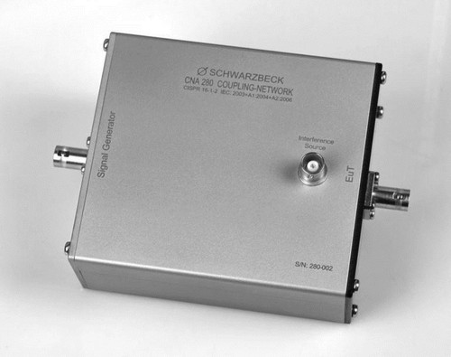
The coupling network CNA 280 is a wired coupling decoupling network (CDN). It meets the specifications of the standard CISPR 16-1-2 A1, figure C1 (unit type A) and is required to calibrate EMI absorbing clamps like the MDS 21. The ground connector of the isolated BNC jack at the EuT side of the device is connected to the inner conductor of the interference source connector via a 100 ? resistor. You can connect a generator to the interference source connector to apply an interference voltage or you can connect an EMC measurement receiver to measure the signals emitted by the EuT.
Such coupling networks are supposed to decouple the equipment under test (EuT) from disturbing high frequency influences of the environment by a certain level. Thus repeatable circumstances get created for the measurement test setup.
The coupling network CNA 280 can be used to put interference current to the device under test. The signal generator input of the CNA 280 is well decoupled from the interference source connector.
One application for the CNA 280 is to check the immunity of RF-receivers where sheath currents get injected to the coaxial input. The test procedure is described in CISPR 16-1-2, chapter 6.
In the standard CISPR 16-1-3, app. B 3.2 this kind of coupling-decoupling-network is specified to check the decoupling factor DR of absorber transducer clamps.
The picture B.9 in the same chapter shows the test setup to measure the decoupling factor of absorbing clamps like the MDS 21 for example.

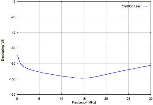
Fig. 1: Decoupling Signal Generator to Interference Port

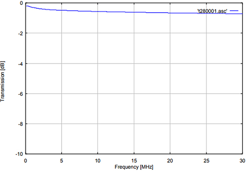
Fig. 2: Insertion Loss Between Signal Generator and EuT port
| Specifications | |
| Frequency range | 9 kHz – 30 MHz |
| Connectors | BNC |
| Impedance of Line A, Line B and output port | 50 ? |
| Voltage division factor at the measuring port | (0 … - 2) dB |
| Material | Aluminium |
| Dimensions (housing W x H x D) | 105 x 49 x 120 mm |
| Weight | 490 g |


