Overview
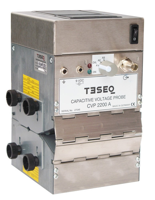
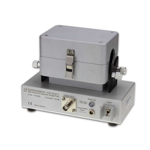
The Capacitive Voltage Probe (CVP) is designed for measuring asymmetrical disturbances on cables with
capacitive coupling principle. It gives the opportunity to do the measuring without disconnection of the
tested cable (“in-situ”) and it avoids the infl uence of the transmission. Main parameter of the CVP is the
coupling factor, measured in a calibration system with 50 Ω impedance. The capacitive voltage probe is
specifi ed in chapter 5.2.2 and Annex G of CISPR 16-1-2.
Application
The Capacitive Voltage Probe (CVP) is used for measuring on telecommunication ports for lines with
more than four balanced pairs or for unbalanced lines.
[split]
- Frequency range: 150 kHz to 30 MHz
- RF voltage range (in relation to a noisefi gure of the receiver F ≤ 10 dB) Sinus voltage (Average, BIF = 9 kHz CISPR 16-1)
- Upper limit (A1, 1 dB- compression): 150 dBμV
- Lower limit (A3, f ≥ 1 MHz, noise error ≤ 1 dB): 26 dBμV
- Pulse voltage (Quasi- peak) Upper limit (A1, Puls frequency: 100 Hz): 74 dBμV
- Overload indicator: for sinus- and pulse voltages
- Correction factor k1 (Only valid for a cable diameter of 22 mm)
- A3: 20 dB
- A2: 30 dB
- A1: 40 dB
- Frequency response correction factor k1
- A3: ±0.5 dB
- A2: ±0.5 dB
- A1: ±1 dB
- Power supply
- internal: 6 x 1.2 V, NiMH- Akku, e.g. 1700 mAh
- external: linear power supply, 230 VAC / 9 VDC
- DC current, typ.: 180 mA
- Battery life, typ.: 8 h
- Cable diameter
- max: 32 mm
- min: 5 mm
- Connectors
- Output to the test receiver: BNC 50 Ω, female
- Input power supply: jack bush, ∅ 3.5 mm
[img-1929-left-thickbox_default]


