


Overview
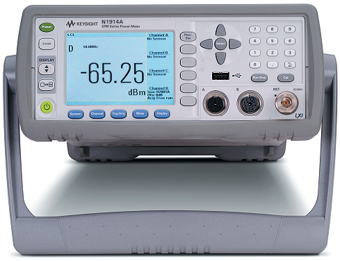
Keysight N1914A EPM Series RF Power Meter
Do More With New-Generation EPM Series Power Meters
- Get up to four channels 1 to speed and simplify RF average power measurements
- Measure faster with improved measurement speed of 400 readings/sec with the Keysight Technologies, Inc. E-Series sensors
- View test results more easily with the industry’s first color LCD readout in an average power meter
- Go beyond GPIB with USB and LAN/LXI-C interfaces
- Automate frequency/power sweep measurements with the optional external trigger in/out feature
- Confirm battery power with a single-button push 2 — and get extra operating time with the optional spare battery
- Easily replace existing 436A, 437B and 438A meters with optional 43x code compatibility 3
- Enhance manufacturing test by connecting a large external monitor with the unique VGA output option
1 Additional two optional USB channels available
2 Only applicable for models with battery option
3 N1913A is backward compatible with the 436A and 437B, while N1914A is compatible with 438A.
Agilent Technologies is introducing the new N1913/1914A EPM Series power meter. It is a replacement for the E4418/4419B EPM Series power meter, and is based on the N1911/1912A power meter platform.
The N1913/1914A offers all average measurement capabilities, comparable to those of the E4418/4419B. However, the N1913/1914A is equipped with a faster digital signal processor (DSP) and microprocessor. Therefore, the N1913/1914A provides better performance than the E4418/4419B. One of the improvements is the measurement speed. When operated with Agilent E-Series power sensors, the N1913/1914A is able to achieve measurement speed up to 400 readings/second, compared to only 200 readings/second on the E4418/4419B.
The N1913/1914A provides enhanced features such as four-channel power measurement (with two additional Agilent USB power sensors connected to the USB master inputs), more connection flexibility (USB slave and LAN [LXI-Class C], on top of the existing GPIB), VGA video output, and smart battery pack.
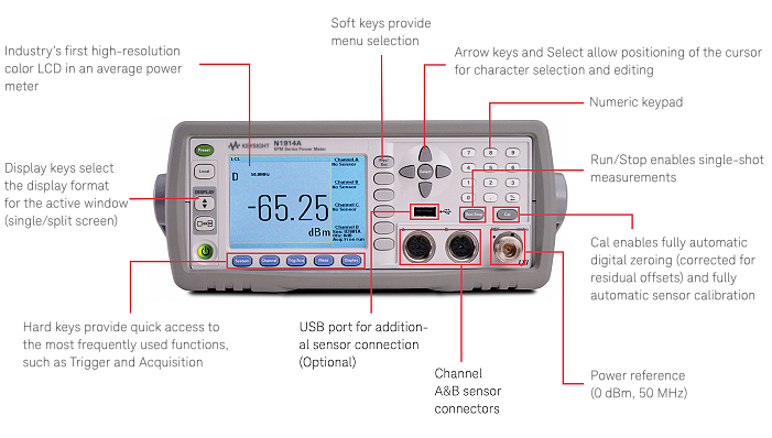
Front Panel
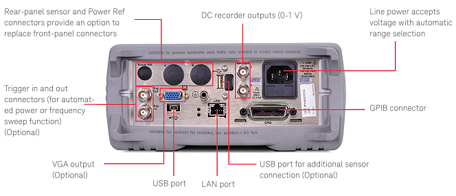
Back Panel
N1913/1914A Operation Overview
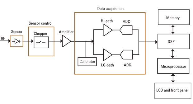
The N1913/1914A operation block diagram shown in Figure 2 is applicable to all Agilent power meters. The meter works with both thermocouple and diode detector mounts, providing accurate RF average power measurement. The sensor converts the high frequency power to a DC or low frequency signal that the meter can then measure and relate to a certain RF power level.
The DC or low frequency signal from the sensor will be chopped, ampli? ed in AC-coupled system, and sent to the meter through the sensor cable. This process is necessary because it is dif? cult to transmit the DC signal across the cable, as the external DC noise will be easily coupled into the original signal. The chopper and AC ampli? er are embedded in the sensor itself. In the meter, the chopped signal is synchronously detected, de-chopped, and ampli? ed again. The calibrator precisely calibrates the signal measured by the meter to a power reference level.
The signal is fed into one of the multi-path blocks after the calibration process. Since most of the Agilent power sensors come with multi-path design, the low path and high path require different gain adjustments for accurate signal measurements. The signal will then be routed to data acquisition where the analog-to-digital converter (ADC) will execute the digital sampling. The essential measurement task is mostly done by the DSP. The microprocessor is the heart of the whole power meter operation, supervising not only data acquisition portion but also all the external interfaces (such as keypad input) and connectivity (remote communication and external triggering).
Operation block diagram of N1913 and 1914A
Faster Measurement Speed
High measurement speed is essential in high-volume manufacturing of RF and microwave components and systems. Faster testing time will improve your productivity by enabling you to test more devices in a shorter time.
Like all the Agilent power meters, there are three types of measurement speed settings for N1913/1914A: normal (by default), double (x2), and fast. In normal and double modes, full sensor functionality is available. In fast mode, averaging limits are disabled and set to 1 that allows fast measurement with uncompromised accuracy.
When the N1913/1914A operates with the E9300 or E4410 Series power sensors, the maximum achievable measurement speed is 400 readings/second in fast mode. The E4418/4419B can only achieve up to 200 readings/second. See Table 1 for specific comparisons of measurement speed.
Because of the SCPI backward compatibility, the same SCPI command for fast measurement mode can be used between the N1913/1914A and the E4418/4419B. Therefore, the N1913/1914A can be used directly by current E4418/4419B users without needing software recoding. For example, using the SCPI command of SENS1:SPE 200 sets the measurement speed on Channel 1 to 200 readings/second. But in reality, the N1913/1914A can achieve up to 400 readings/second in fast measurement mode while the E4418/4419B achieves 200 readings/second only.
Four-Channel Power Measurement
|
|
The new N1914A supports up to four channels for power measurement. There are two optional add-on channels for use with the Agilent U2000 Series USB power sensors in addition to the two channels for conventional Agilent power sensors. The additional two USB power sensors can be connected to the front and rear panel USB ports of the N1913/1914A. The N1914A is able to display four power measurement (average only) readings if all four channels are connected with power sensors. By default, the power meter will display Channel A on the upper window and Channel B on the lower window when two sensors are connected to the meter. |
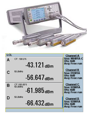
One of the application examples for multiple-channel power measurement is the two-port load-pull system shown in Figure 4. Channel A shows the incident power to the device under test (DUT), Channel B represents the reflected power, and Channel C shows the output power from the DUT. While monitoring all the power measurement results on the meter (Channels A, B, and C), the output tuner is adjusted until the reflected power is zero (Channel B). The gain and the power-added efficiency (PAE) can then be directly measured and displayed on the meter.
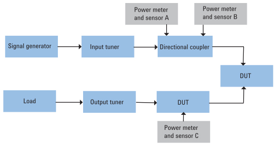
Typical load-pull application with three channels of power measurement
|
Smart battery’s one-push button on N1913/1914A (optional) |
Smart Battery PackLike the E4418/4419B, the N1913/1914A also comes with a battery pack option, allowing users to take measurements in remote areas where AC outlets are not available. The battery pack used in the N1913/1914A is a smart-type battery capable of communicating with the FPGA system and the smart battery’s charger controller. The battery pack uses a system-level approach to optimize the performance of the battery. There are additional safety features such as protection from over-charging and over-discharging as well as passive safety devices for short-circuit and thermal protection. The new battery pack also has one-push-button activation with an LED indicator (as shown in Figure 5) that displays information about battery capacity without requiring the user to turn on the power meter.
The indicator is a four-level LED system, with each level representing different battery power capacity as shown in Table 2. |
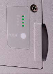
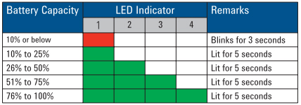
Table 2. LED Power Level Indicator provides information about battery capacity
For the single-channel N1913A, the operation duration of the battery pack is 330 minutes with backlight off and 210 minutes with backlight on. The maximum charging time of the battery pack is approximately two hours when the N1913/1914A is in standby mode with the AC power connected.
Faster Frequency/ Power Sweep Measurement
Frequency/power sweep measurement is typically used to achieve flatness calibration of signal sources. The signal source can be simply the signal generator. In conventional applications, users must manually change the frequency/power of signal source before the measurement is taken and displayed on the front panel of the meter. The setup process is very tedious and time-consuming. An N1913/1914A optional feature utilizes the physical external trigger in/trigger out (via BNC cables) for both power meter and signal generator to reduce the testing time dramatically.
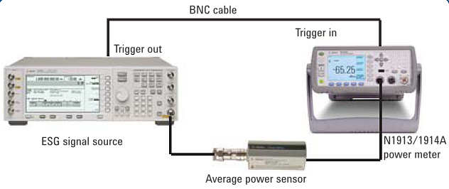
A setup example is shown in Figure 6, where the N1913/1914A is connected to Agilent E4438C ESG signal source. The trigger out of the signal source is connected to the trigger in of the power meter. The trigger out of the power meter is connected to the trigger in of the signal source. Users must define the start, stop, and step frequency for signal source and power meter. The signal source will step to the first frequency point and then generate a trigger out signal to the power meter. The power meter will start data acquisition. Once the measurement is settled, the power meter will output a trigger to the signal source so that the signal source will step to the next frequency point. This process continues, repeating itself for every frequency step.
Every triggered measurement will be stored in a buffer in the power meter, the size of which is user-defined (1 to 2,048). Once the measurement cycle is completed, the data stored in the buffer can be retrieved by using SCPI.
Conclusion
The N1913/1914A EPM Series power meter is an enhanced version of the E4418/4419B EPM Series power meter. The additional features and the improved user interface make the new N1913/1914A the best choice for any type of average (CW or modulated) power measurement.
| SPECIFICATIONS | ||||||
| N1913A/14A EPM Series Power Meters Performance Characteristics | ||||||
| Frequency Range | 9 kHz to 110 GHz, sensor dependent | |||||
| Power Range | –70 to +44 dBm (100 pW to 25 W), sensor dependent | |||||
| Single Sensor Dynamic Range | 90 dB maximum (Keysight E-Series power sensors) 50 dB maximum (Keysight 8480 Series power sensors) 55 dB maximum (Keysight N8480 Series power sensors) 80 dB maximum (Keysight U2000 Series USB power sensors) |
|||||
| Display Units | Absolute: Watts or dBm Relative: Percent or dB |
|||||
| Display Resolution | Selectable resolution of: 1.0, 0.1, 0.01 and 0.001 dB in logarithmic mode, or 1, 2, 3 and 4 significant digits in linear mode | |||||
| Default Resolution | 0.01 dB in logarithmic mode or three digits in linear mode | |||||
| Accuracy | ||||||
| Absolute Accuracy | ± 0.02 dB (Logarithmic) or ± 0.5% (Linear). Please add the corresponding power sensor linearity percentage from Tables 6, 9 and 10 (for the E-Series sensors), Table 14 (for the 8480 series sensors) and Table 16 (for N8480 sensors) to assess the overall system accuracy. | |||||
| Relative Accuracy | ± 0.04 dB (Logarithmic) or ± 1.0% (Linear). Please add the corresponding power sensor linearity percentage from the mentioned tables above to assess the overall system accuracy. | |||||
| Zero Set (Digital settability of zero) | 0.0000175% (meter only) Power sensor dependent (refer Table 1), this specification applies when zeroing is performed with sensor input disconnected from the POWER REF. |
|||||
| Zero Drift of Sensors | This parameter is also called long term stability and is the change in the power meter indication over a long time (within one hour) at a constant temperature after a 24-hour warm-up of the power meter. Sensor dependent, refer to Table 1. For E9300 sensors, refer to Table 11 for complete data. | |||||
| Measurement Noise | ||||||
| Effects of Averaging on Noise | Averaging over 1 to 1024 readings is available for reducing noise. Table 1 provides the measurement noise for a particular power sensor with the number of averages set to 16 for normal mode and 32 for x2 mode. Use the “Noise Multiplier” for the appropriate mode (normal or x2) and number of averages to determine the total measurement noise value. For example: For a Keysight 8481D power sensor in normal mode with the number of averages set to 4, the measurement noise is equal to: (< 45 pW x 2.75) = < 124 pW |
|||||
| 1 mW Power Reference | ||||||
| Power Output | 1.00 mW (0.0 dBm). Factory set to ± 0.4 % traceable to the National Physical Laboratories (NPL), UK | |||||
| Accuracy (For Two Years) | ± 0.4% (25 ± 10 ºC) ± 1.2% (0 to 55 ºC) |
|||||
| Frequency | 50 MHz nominal | |||||
| SWR | 1.05 (typical), 1.08 (0 to 55 ºC) | |||||
| Connector Type | Type-N (f), 50 ? | |||||
| Measurement Speed | ||||||
| With N1914A Power Meter | The measurement speed is reduced, for example, with both channels in FAST mode, the typical maximum measurement speed is 200 readings/second. | |||||
| Fast mode is for Keysight E-Series power sensors only. | ||||||
| Maximum measurement speed is obtained using binary output in free run trigger mode. | ||||||
| Power meter functions | ||||||
| Accessed by Key Entry | Either hard keys, or soft key menu, and programmable | |||||
| Zero | Zeros the meter. (Power reference calibrator is switched off during zeroing.) | |||||
| Cal | Calibrates the meter using internal (power reference calibrator) or external source. Reference cal factor settable from 1% to 150%, in 0.1% increments. | |||||
| Frequency | Entered frequency range is used to interpolate the calibration factors table. Frequency range from 1 kHz to 999.9 GHz. Also settable in 1 kHz steps. | |||||
| Cal Factor | Sets the calibration factor for the meter. Range: 1% to 150%, in 0.1% increments. | |||||
| Relative | Displays all successive measurements relative to the last displayed value | |||||
| Offset | Allows power measurements to be offset by –100 dB to +100 dB, settable in 0.001 dB increments, to compensate for external loss or gain | |||||
| Save/recall | Store up to 10 instrument states via the save/recall menu | |||||
| dBm/W | Selectable units of either Watts or dBm in absolute power; or percent or dB for relative measurements | |||||
| Filter (averaging) | Selectable from 1 to 1024. Auto-averaging provides automatic noise compensation. | |||||
| Duty cycle | Duty cycle values between 0.001% to 99.999%, in 0.001% increments, can be entered to display a peak power representation of measured power. The following equation is used to calculate the displayed peak power value: peak power = measured power/duty cycle. | |||||
| Sensor cal tables | Selects cal factor versus frequency tables corresponding to specified sensors | |||||
| Limits | High and low limits can be set in the range –150.000 to +230.000 dBm, in 0.001 dBm increments | |||||
| Preset default values | dBm mode, rel off, power reference off, duty cycle off, offset off, frequency 50 MHz, AUTO average, free run, AUTO range (for E-Series sensors and N8480 Series) | |||||
| Display | Color display with selectable single and split screen formats are available. A quasi-analog display is available for peaking measurements. The dual channel power meter can simultaneously display any two configurations of A, B, A/B, B/A, A-B, B-A and relative. With the optional USB ports, additional dual channel (C & D), adds up to total 4-channels measurement display. | |||||
| Rear panel connectors | ||||||
| Recorder outputs | Analog 0 to 1 volt, 1 k? output impedance, BNC connector. N1914A recorder outputs are dedicated to channel A and channel B | |||||
| GPIB, USB 2.0 and 10/100BaseT LAN | Interfaces to allow communication with an external controller | |||||
| Trigger Input (optional) | 1 Input has TTL compatible logic levels and uses a BNC connector High: > 2.4 V Low: < 0.7 V |
|||||
| Trigger Output (optional) 1 | Output provides TTL compatible logic levels and uses a BNC connector High: > 2.4 V Low: < 0.7 V |
|||||
| Ground | Binding post, accepts 4 mm plug or bare wire connection | |||||
| USB Host (options | USB ports which connects to U2000 series USB power sensors | |||||
| VGA Out (options) | Standard 15-pin VGA connector, allows connection of external VGA monitor | |||||
| 1. For automated power or frequency sweep function. | ||||||
| Line Power | ||||||
| Input voltage range | 90 to 264 VAC, automatic selection | |||||
| Input frequency range | 47 to 63 Hz and 400 Hz at 110 Vac | |||||
| Power requirement | 75 VA (50 Watts) | |||||
| Battery option operational characteristics 1 | ||||||
| The following information describes characteristic performance based at a temperature of 25 °C unless otherwise noted. | ||||||
| Typical operating time | Up to 6 hours with LCD backlight on; up to 7.5 hours with LCD backlight off (N1913A power meter) | |||||
| Charge time | Approximately, 2.5 hours to charge fully from an empty state. Power meter is operational whilst charging. | |||||
| Battery type | Lithium-ion (Li-ion) | |||||
| Battery storage temperature | –20 to 60 °C, ≤ 80 % RH | |||||
| Environmental Characteristics | ||||||
| Electromagnetic compatibility | Complies with the essential requirements of EMC Directive (2004/108/EC) as follows: IEC61326- 1:2005 / EN61326- 1:2006 CISPR11:2003 / EN55011:2007 (Group 1, Class A) |
|||||
| The product also meets the following EMC standards | Canada: ICES/NMB- 001:2004 Australia/New Zealand: AS/NZS CISPR 11:2004 |
|||||
| Product safety | This product conforms to the requirements of the following safety standards: IEC 61010- 1:2001 / EN 61010- 1:2001 : CAN/CSA- C22.2 No.61010- 1- 04 : ANSI/UL61010- 1:2004 | |||||
| Low Voltage Directive | This product conforms to the requirements of European Council Directive “2006/95/EC” | |||||
| Operating Environment | ||||||
| Temperature | 0 to 55 °C | |||||
| Maximum humidity | 95% at 40 °C (non-condensing) | |||||
| Maximum altitude | 4,600 meters (15,000 feet) | |||||
| Storage Conditions | ||||||
| Non-operating storage temperature | –40 to +70 °C | |||||
| Non-operating maximum humidity | 90% at 65 °C (non-condensing) | |||||
| Non-operating maximum altitude | 4,600 meters (15,000 feet) | |||||
| Remote Programming | ||||||
| Interface | GPIB, USB and LAN interfaces operates to IEEE 488.2 standard Command language SCPI standard interface commands. Code-compatible with legacy E4418B/9B EPM Series, 436A, 437B and 438A power meters (43X compatibility only with option N191xA-200). | |||||
| GPIB compatibility | SH1, AH1, T6, TE0, L4, LE0, SR1, RL1, PP1, DC1, DT1, C0 | |||||
| 1. Characteristics describe product performance that is useful in the application of the product, but is not covered by the product warranty | ||||||
| Power meter General Specifications | ||||||
| Dimensions | The following dimensions exclude front and rear protrusions: 212.6 mm W x 88.5 mm H x 348.3 mm D (8.5 in x 3.5 in x 13.7 in) | |||||
| Weight | 3.7 kg (8.2 lb) | |||||
| Shipping Weight | 8.2 kg (18.3 lb) | |||||


")

