Overview
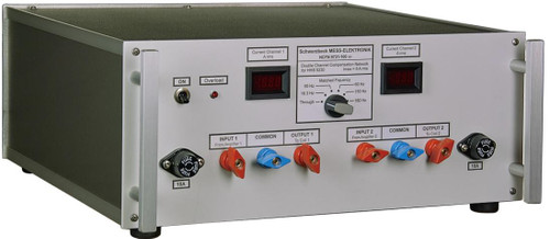
The primary function of the compensation network NFCN 9731 is to provide a serial compensation of the inductance of the HHS 5206-16. Thus the currents needed to produce the desired field strength can be achieved using relatively low voltages i.e. to be able to use an audio amplifier.
The compensation capacitor of the NFCN 9731 reduces the overall impedance of the series circuit with the Helmholtz coil HHS 5206-16 at the wanted operating frequency and allows currents up to 30 Arms at a generator voltage of less than 40 Vrms. An integrated shunt allows measuring the coilcurrent and serves as minimum load for the power amplifier.
The compensation network NFCN 9731 consists of a series circuit of a variable capacitor and a fuse. Its purpose is to compensate the inductance of the Helmholtz coil HHS 5206-16 at operating frequencies of 180 Hz up to 200 kHz. Up to 180 Hz no compensation is necessary and the signal is looped through.
There are 23 different capacitors and a short available. They are connected between “Power Amplifier” and “Coil (to A)” utilizing relays.
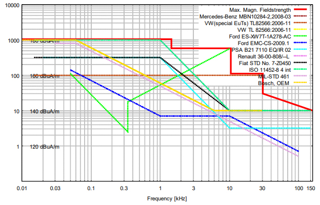
The following graph shows the maximum reachable magnetic field strength of the system (HHS 5206-16, NFPA 9730 and NFCN9731) – in relation to common standards.
Max. magnetic fieldstrength of HHS 5206-16 with NFPA 9730, NFCN 9731

Internal 1 Ohm Shunt
The integrated 1 Ohm (800W) shunt allows measuring the coil-current and serves as minimum load for the power-amplifier. The internal fans are automatically enabled if the shunt becomes hot.
The shunt can be used stand-alone without the compensation network. But the cooling fans are only working when NFCN 9731 is turned on.
The following chart shows the total impedance of the shunt versus the frequency.
| Frequency, [kHz] | Impedance “1Ω”, [Ω] |
| DC | 0.999 |
| 10 | 0.999 |
| 20 | 1.000 |
| 30 | 1.001 |
| 50 | 1.003 |
| 80 | 1.009 |
| 100 | 1.014 |
| 120 | 1.019 |
| 150 | 1.027 |
| 200 | 1.043 |
| 250 | 1.060 |
| 300 | 1.079 |
Internal low level signal attenuator
The internal switchable low level signal attenuator increases the dynamic range of the system. Therefore the attenuator is interconnected between the signal generator and the amplifier with a BNC-cable (Signal generator to the “IN” socket. The “OUT” socket to the input of the amplifier).
The attenuation of 0 dB, 20 dB or 40 dB can be switched by the relays-control-word. The signal is muted if no attenuation is set.
At low output levels the level step size of most signal generator is to big. In this case an attenuator can be used. The signal generator has to compensate the attenuation with higher output levels. Now the relationship of the step size to the output level is smaller.
Hazard warning
Attention: Life-endangering high voltages occur at the terminals of the HHS 5206-16 and the NFCN 9731 during operation. If used in an inappropriate way this could lead to a life-threatening situation for the user.


