Overview
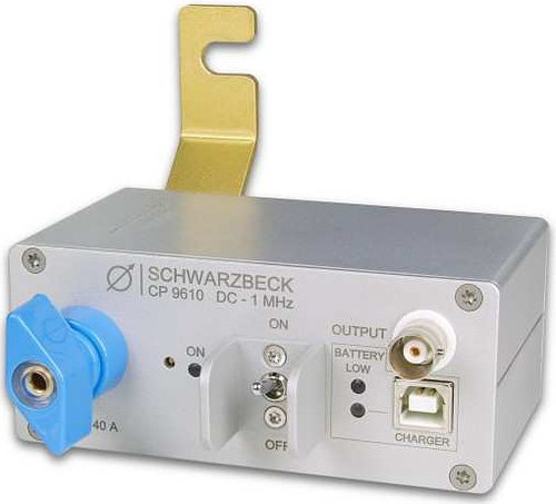
The current sensor CP 9610 can measure up to 40 A in a frequency range from DC – 1 MHz. It is galvanically isolated and can withstand a maximum voltage of 210 VPK / VDC. The internal resistance of the conductive path is less than 3 m?, providing low power loss. The hall transducer is temperature compensated and allows high accuracy over temperature.
To adjust the output voltage to zero, ensure that the probe is disconnected from current carrying conductors. The offset can be adjusted with the potentiometer “ZERO ADJUST” by using a suitable screwdriver.
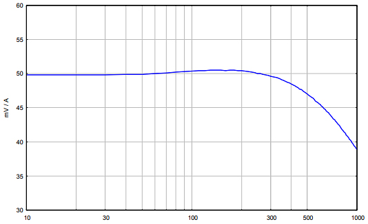
The nominal conversion factor is 50 mV / A. The range of measurement is ± 40 A. The output voltage is proportional to the current and is up to ± 2 V.
If the current flows like pictured during the arrow at the case the output voltage will be positive. To mount the CP 9610 to our compensation network NFCN 9734 a mounting bracket is included at the scope of delivery.
Beginning of Operation
Operation environment
The CP 9610 is preferably used indoors. While using on open area test sites, it must be protected from weather conditions, especially humidity.
Switching ON
The device is turned on with the pilot-style power-switch. Push the switch to the upper side. The green LED “On” indicates the proper charged battery. The red LED “Low Bat” means the battery is nearly empty. If the LED is dark even while the generator is turned on the rechargeable battery is disconnected because of low voltage. After charging the unit will be ready for operation.
More information about the battery
The CP 9610 is equipped with a 3.7 V Lithium cell. The battery voltage is indicated with a green LED for normal operation. If the red LED “Low Bat” is illuminated recharge is required. A full battery charging period using the USB port takes around 5 hours. While recharging the yellow LED “Charge” is illuminated. The power-switch should be set to OFF during the recharging period. It is possible to measure during recharging. But disturbances generated by the charger could have an unwanted influence on the measurement.
A special circuit prevents the battery from being discharged completely. Whenever the voltage is too low for battery health or measurement precision, it will be automatically disconnected from the load. When the CP 9610 is switched ON and the red LED below is dark, this isolation has taken place. In this case the battery must be charged immediately. The second best advice is to switch OFF the CP 9610 to avoid the (very low) idle current of the protection circuit.
Current Probe CP9610

Frequency [kHz]
 |
 |
Warning Use caution when working with voltages above 60 VDC, 30 VAC rms or 42 VAC peak. Such voltages pose a shock hazard.
| Specifications | |
| Frequency Range | DC – 1 MHz |
| Output Connector | BNC (1 MOhm) |
| Current Sensing Range | -40 A - +40 A |
| Nominal conversion factor | 50 mV/A |
| Internal Conductor Resistance | < 3 mOhm |
| Typical Output Error | ±3 % |
| Dimension | 105 x 44 x 115 mm |
| Typical Operation Time | 24 h |
| EuT Connectors | Wing terminals |
| Power Supply | 3.7 V, 2.6 Ah Lithium Ion |
| Weight (incl. Battery) | 430 g |


