Overview
- Engineered and completely manufactured both in Italy and Brazil.
- Ruggedized fully hot galvanized steel construction (INOX steel optional)
- Unique compact design.
- Optimized for EMI and EMC
Operation
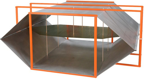
Transverse Electro Magnetic (TEM) cell or Crawford cell (named after its inventor) is used to generate accurate electromagnetic waves over a wide frequency range: DC (0 Hz) to GHz. EM waves generated in the cell propagate in transverse mode and have the same characteristics as a plane wave. It can be used to calibrate E-field broadband probes for testing radiated E-field immunity as well as for measuring radiated emission from a product with a spectrum analyzer/EMI receiver.TEM cell generates a consistent electromagnetic field for testing small RF devices such as wireless pagers, receivers, portable phones, etc. An external test signal applied through the input port of the TEM cell generates a consistent and predictable (plane wave) test field inside the TEM cell. The radiation field emanating from a device (under test) located in the cell can also be detected through the signal generator port connected to an EMI receiver or a spectrum analyzer. The Equipment Under Test (EUT) is placed on the bottom ground plane as in Open Area Test Site (OATS) and in accordance with the shielded enclosure conditions. TEM cells are used in final compliance certification tests. There IEC 61000-4-3 EMC standard, require a TEM cell for radiated susceptibility and radiated emission tests. Integrated Circuits (IC), Micro Electro-Mechanical Systems (MEMS) devices and PCBs can also be tested according to the standard SAE J1752-3 . TEM cells can deliver an equivalent OATS performance inside the comforts of a lab with minimum OATS errors. The main advantage of a TEM cell over a strip-line is that in the former, the EUT is completely shielded (except a window to insert/monitor the EUT) from the external environment, thus producing results with negligible errors. It is one of the reasons why a TEM cell is qualified to perform final compliance tests.The GTEM cell is a TEM waveguide with the upper frequency limit extended to the GHz range. It is a low-cost alternative measurement facility for both radiated emission and immunity measurements. It is included in the recently published standard IEC/EN 61000-4-20 “Emission and Immunity Testing in Transverse Electromagnetic (TEM) Waveguides”. Compared to other measuring methods like EMC test in anechoic chambers or OATS (Open Area Test Sites), GTEM-cells offer some significant advantages for the testing of small and medium sized EUT´s (Equipment Under Test) up to a frequency range of 20 GHz. Quick turnarounds of the EUT as well as numerous testing variations are easy and fast to handle. Switching from emission to immunity testing requires only simple adjustments from receiver input to amplifier output. You are irrespective of long waiting times associated with off-site test labs or weather and ambient delays that can occur at OATS facilities.
Applications
- EMI and EMS devices
- Radiation and susceptibility test
- Specifically designed for telecom application
- Biomedical and dosimetrical applications
- Isotropic sensors calibration
- Receiver sensitivity test
- Antenna pattern
- Shielding effectiveness caracterization test
Specifications
- Frequency range DC-200 MHz
- Height under the plate 27 cm
- Dimensions (LxWxH) 200x95x62cm
- Max. Input power 1,6KW long term
- Field for a 25W amplifier
- 118V/m
- Impedance 50 ohm
- VSWR <1.1
- Return Loss >25dB
- Connector type N
- Weight Approx. 40Kg


