Overview
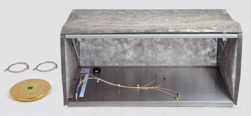
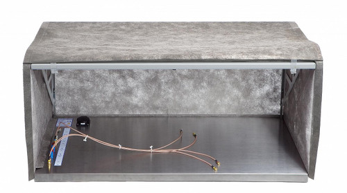
The PT4 Set is used to analyze immunity of assemblies and devices efficiently. The PT4 burst transformer converts the pulses of the EFT/burst generator into potential free burst pulses. These are injected into individual sections of the device under test, enabling the developer to locate its susceptible areas. The set includes a magnetic and an electric field source which are also supplied by the EFT/burst generator. The field, which emerges from the head of the field source, is used to scan the surface of the device under test. This allows the weak spots to be located with precision and assigned to the fault patterns that occur in compliance tests. The burst transformer and the connecting cable come with either an SHV plug (HV SHV-SMB 1 m) or a Fischer plug (HV FI-SMB 1 m). Please select the desired connector/plug when ordering.
Measurements taken with an oscilliscope during interfence are possible because the pulses from the burst generator are galvanically isolated. This allows for a significant reduction in faulty measurements despite possible interference.
Mode of operation
Burst generators generate burst pulses relative to their enclosure. The enclosure is connected to a metal plate below the equipment under test (EUT) for measurements in conformance with the relevant standards.
This results in a measurement set-up as shown in Figure 1.
Disturbance current is injected into the EUT via an artificial mains network or a coupling clamp. This current flows through the EUT on largely unknown paths and then, by capacitive coupling, into the metal plate. If any malfunctions occur, the coupling mechanisms and coupling locations have to be precisely determined as quickly as possible.
In addition to using field sources for troubleshooting, the developer has two other possibilities:
a) to inject disturbance current into the EUT section by section and thereby locate the fault step by step.
b) to measure signals from the EUT under the influence of disturbances and thus detect the cause of the malfunction.
Both procedures are limited in practice by the burst voltage relative to the generator enclosure:
to a) If a disturbance current is injected at any point on the EUT and a second point is connected to the generator enclosure, a burst current flows between these two points as desired. However, another burst current flows between the injection point and the generator enclosure via parasitic coupling paths (e.g. capacitive GND - PE connection in the EUT and back to the burst generator via PE). The burst current can also cause malfunctions on this path and thus lead to a false measurement result.
to b) If the measurement is taken during the disturbance and the probe of an oscilloscope, for example, is connected to the EUT for this purpose, a part of the disturbance current flows to the oscilloscope parallel to the actual disturbance current path via the GND connection of the probe (Figure 2). The disturbance current is thus modified in the EUT, a voltage drop is caused on the probe and measuring lead shield, which is also measured, and the oscilloscope may be influenced.
The PT4 isolates the output pulse of the burst generator from the generator. The connection cable of the PT4 contains attenuation elements that also prevent high-frequency common-mode currents from flowing from the generator to the EUT. It is thus possible to take the measurements described under a) and b) without any disturbing parasitic currents.
Usage
General notes
The high-voltage plug of the PT4 is connected to the burst output socket of a burst generator. The maximum supply voltage is 4.5 kV (peak value). The generator setting "Burst voltage positive“ corresponds to a positive voltage pulse on the red PT4 output socket or a negative voltage pulse on the blue one.
Both PT4 outputs are capacitively decoupled. It is thus possible to inject a disturbance current in Vcc, for example, and to decouple via GND.
Components can be damaged if the injected current is too high. Always start the measurement at the lowest generator setting. You should provide means to quickly switch off the EUT and generator in the event of a malfunction.
Despite being careful the EUT may be destroyed in exceptional cases.
Injecting disturbance current
(comparison of malfunctions)
| Disturbance current can be coupled to GND/Vcc conductor runs, cable shields, shield connections, auxiliary power lines, discharge capacitors. Connect the PT4 outputs directly to the EUT via the enclosed clips. The injection points should be selected in the following way: First try to simulate the natural path of the disturbance current through the EUT. To do so, establish a conductive coupling to the shield or shield connection of a connected cable, for example (Figure 3). The disturbance current flows through the EUT and is led out of the EUT enclosure, for example, back to the PT4. Instead of coupling to the cable shield, you can also inject the disturbance current directly into individual cores of a cable (Figure 4). As an alternative you can use a piece of aluminium foil to simulate a shield (Figure 5). The objective of this examination is to simulate the malfunction that occurs in compliance testing and to find potential disturbance current paths in the device. If you have caused any malfunction, try to locate the fault more precisely in subsequent measurements by injecting the current to the EUT section by section. |
Figure 3 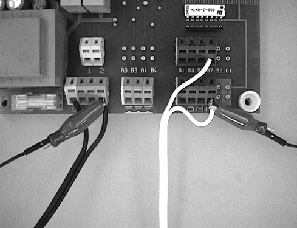 Figure 4 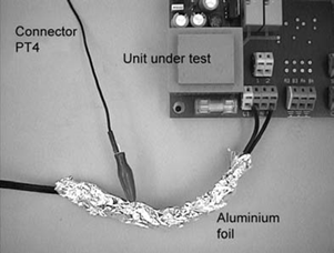 Figure 5 |

Figure 6
Some possibilities to inject disturbance current are shown in Figure 6. For example, you can examine the characteristics of the ribbon cable between both circuit boards by injecting the current in the GND layers of both circuit boards very close to the pin-and-socket connectors.
Measuring signals with an oscilloscope
The following measurement set-up should be used to ensure a satisfactory measurement of signals during burst pulse injection: Set up the burst generator on a wooden table as far away as possible from the EUT. Use the full length of the PT4 connecting cable (Bild 7).
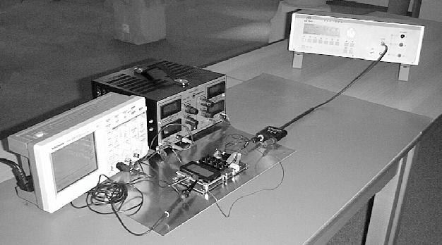
Bild 7
You can twist the cables from the PT4 up to the EUT to reduce magnetic coupling between the cable and the EUT.
Put the EUT on a metal base. Connect the GND of the EUT and the GND of the applied measuring instruments electrically to this metal plate (Bild 7, Figure 8). Voltage differences and hence transient currents between the EUT and measuring instruments can thus be reduced considerably.

Do NOT connect this plate to the burst generator!
Place the measuring lines as close as possible to the metal plate to minimize magnetic coupling between the lines carrying the disturbance current and the measuring lines.
Even if the EUT is very large or mounted in a switch cabinet, for example, set up the burst generator as far away as possible from the EUT. Twist the lines from the PT4 to the EUT as far as possible.
A fibre-optics system has to be used (e.g. A50 for analogue systems or OSE50 for digital ones) if the measuring errors are not small enough.
Disturbance Mechanisms
- Electronic modules have different disturbance immunities depending on their layout and IC sensitivity.
- Weak points, which can be exactly pinpointed, are the cause of burst and ESD susceptibility. The occurrence of weak points depends to a large extent on the GND / Vcc / signal conductor run geometry and type and/or manufacturer of the installed ICs.
- Disturbance current (i) enters the electronic module either conducted or capacitively and produces electric (electric field intensity E) and magnetic (magnetic flux density B) disturbance fields on the module surface.
- Magnetic (B) or electric (E) pulse fields are the essential physical parameters that cause an effect on printed-circuit boards. As a rule, a weak point is either only magnetically or only electrically susceptible.
- From a practical point of view, both types of weak points are relevant. For example, electric fields can occur during disturbance events which trigger a response from electrically susceptible weak points. The currents which are driven by the electric field produce magnetic fields which, in turn, trigger a response from magnetically susceptible weak points (Figure below).
- The disturbance effects of both mechanisms overlay one another and are difficult to separate. Both types of weak points require different EMC measures due to their differing physical mechanisms. There are mostly only a few disturbance immunity weak points on a module which are often limited to small surface sections. The module is immune to disturbances when the disturbance immunity weak points have been found and remedied.
Fields within an EUT - an example:

Figure 9
Disturbance current ( i ) enters the device by conduction. The share iA is diverted on discharge current paths to the outside via the capacitors C. The disturbance current iI is thus reduced in the inner sections. The magnetic fields B shown in the Figure can influence electronic modules that are placed several decimetres away. Not all B fields that permeate the module's surface have an influence. Mostly only small areas are susceptible to B fields. It should be remembered that not only disturbance currents (i) produce magnetic fields in the vicinity of supply cable and PE connections. Discharge paths that go via discharge capacitors C and internal GND and Vcc connections are largely involved. Electric pulse fields E are produced by the lines carrying disturbance currents that mostly influence signal connections having high-resistance signal sources.
Safety Instructions
- Do not use any damaged or defective devices.
- Max. supply voltage of the PT4: 4.5 kV burst.
- Only connect and disconnect the PT4 when it is disconnected from the mains.
- Start the tests at the lowest generator voltage setting.
- Only operate the PT4 with burst generators that comply with EN 61000-4- 4.
- Observe the operating instructions for the respective burst generator that is used.
- Only use the PT4 for electronic devices and modules that are defined as an EUT.
- Only personnel who are qualified in the field of EMC and experienced in working under the influence of electric and magnetic burst fields may use the PT4.
- Only operate the test set-up via a filtered power supply
- Attention! When using the PT4 with a burst generator, near fields can develop and disturbances emitted due to its function. The user is responsible for taking measures to guarantee that the normal use of products installed outside the EMC operating environment is not effected (particularly by disturbance emission).
This can be done by:
- making sure that there is an adequate safety gap
- using shielded or shielding rooms
- Due to their functionality and in case the effect on the EUT is too strong, the fields produced by the PT4 can destroy ICs (latch-up). Protection can be provided by:
- not increasing the generator voltage if malfunctions occur.
- quickly interrupting the power supply of the EUT in case of latch-up.
Technical data
Scope of delivery
1x PT4, Burst Transformer
1x BS 04DB-h, Magnetic Field Source
1x ES 05D-h, E-Field Source
1x HV SHV-SMB 1 m, High-Voltage Cable, SHV SMB
1x PT4 acc, Accessories
1x PT4 case, System Case
1x PT4 m, PT4 Set User Manual
| Technical Data | |
| PT4 Burst Transformer | |
| Maximum supply voltage | 4.5 kV burst |
| Transformation ratio | 1:1 |
| Dielectric strength of the outputs (direct voltage, 50 Hz alternating voltage) | 500 V |


