Overview
The LFCI4-16/19 is a common and differential mode disturbance test generator for the frequency range from DC up to 300 kHz. The internal 250 watt amplifier will generate an output signal up to 5 Amps (16 amps available) with a voltage gain of factor 10. Full software control with pre programmed test sequences to IEC/EN 61000-4-16 and IEC/EN 61000-4-19 and allows easy signal generation at a desired frequency and voltage output as well. Internal safeguards assure protection against external faults. Signals are generated by an internal generator, its output signals are amplified by an amplifier module. Different signal types as sine, triangular or square wave are selectable. Further user defined signals can also be added via an external input.
EMC Applications
IEC/EN 61000-4-16 - Test for immunity to conducted, common mode disturbances in the frequency range 2 kHz to 150 kHz at a.c. power ports
IEC/EN 61000-4-19 - Test for immunity to conducted, differential mode disturbances and signalling in the frequency range 0 Hz to 150 kHz
General Applications
For almost any electronic engineer or technician it is necessary to generate a strong output signal. Using th LFCI4-16/19 stable output signals are generated and amplified within a wide frequency range.
Automatic Testing
Several standards for EMC testing require high output signals and low distortions. Excellent signal quality and full remote control allows the usage of the LFCI4-16/19 as automatic testing equipment.
Driving low impedances
Voltage supply level can be halved during LFCI4-16/19's operation which result in lower power dissipation for low impedance loads (e.g. Helmholtz coils).
Waveforms
Three different waveforms can be generated using a LFCI4-16/19: sine wave, triangular and rectangular signals. Frequencies from DC up to 300 kHz can be generated at a resolution of 0.05 Hz. Adding a common mode voltage is also possible for any signal type.
Technology
Full linear design allows to amplify signals with low distortion, low noise and high stability. Two different voltage supply levels optimize the power dissipation when driving a low impedance load.
Safeguards
Several safeguards are implemented to protect the amplifier from any external fault, e.g. short-circuit and overheating due to high power dissipation.
Software control
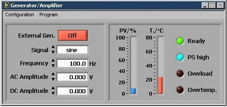
An USB interface allows to control and monitor all internal functions via an external application. A software application is included and the interface commands are described to integrate the LFCI4-16/19 into an existing automatic test system.
Typical Characteristics
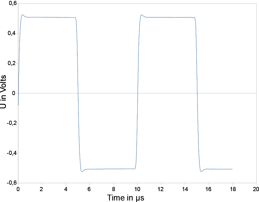 Square wave at 100 kHz (small signal) ± 500 mV |
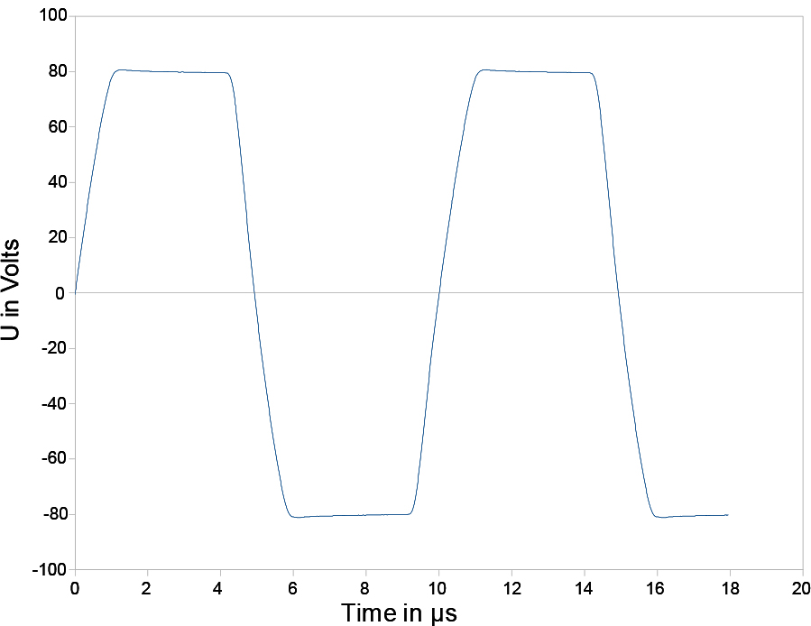 Square wave at 100 kHz (large signal) ± 80 V |
| Specifications | |
| Electrical Data / Amplifier | |
| Frequency range | DC – 1 MHz (Small signal -3 dB) |
| Power bandwidth | DC – 200 kHz |
| Slew rate | 100 V/µs |
| Offset | ± 1 mV (± 0.1 mV / °C) |
| Voltage gain | 10 ± 0.1 % (± 0.01 % / °C) |
| Output voltage | 50 Vrms / ± 75 Vpeak |
| Output current | 5 Arms / ± 7.5 Apeak |
| Distortion (DC – 100 kHz, load ≥ 4 Ohms) | < 0.10% |
| Input impedance | 100 kOhms |
| Max. input voltage | 80 V (cont.), 100 V (< 1 min) |
| Noise (10 Hz – 1 MHz, Input 50Ohms) | 0.5 mVrms |
| Power dissipation (each side) | 260 W (100 ms) |
| Primary power | 230 VAC / 50 Hz |
| Remote control | USB |
| Generator | |
| Frequency range | DC, 0.05Hz - 300 kHz; resolution 0.05 Hz |
| Frequency accuracy | ± 20ppm |
| Signal types | Sine , triangle and square waveforms |
| Mechanical Data | |
| Dimensions (W x H x D) | 17.6" x 5.25" x 17" mm |
| Weight | Approx. 30 Lbs |


