Overview
A tuned Half-Wave Dipole Antenna is considered as a reference for the measurement of field strength and for the generation of defined UHF electromagnetic fields (up to 10 watts erp).
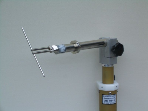
The model UHA 9105 Antenna consists of the aerial head with a teflon coax BALUN that provides symmetry up to 1 GHz and two tubes, slotted at their ends and tightened by hexagonal nuts.
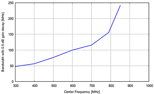
Without the telescopic inserts the total tube-element length is 120 mm. With the telescopic elements a total length range is 173 mm to 520 mm. Generally the bandwidth is high due to the large diameter/length-ratio, particularly from 800 MHz up.
The Antenna Holder is a 475 mm tube with a diameter of 22 mm with an indexing ring, fixed with 3 mm screws to provide a fixed position with the elements in a vertical or horizontal plane when inserted in the movable antenna holding box of the detachable mast system model AM 9104 for antenna heights from 0.4 m to 4 m.
Schwarzbeck UHA 9105 Adjustment of Dipole length:
The dipole length adjustment is not critical due to the large bandwidth of the elements with a high diameter to length ratio. In contrast to slim elements, the length may differ a few millimeters (show Table 1).
It is recommended to extend first the element sections with a thicker diameter. In that way the dipole-elements gets a better diameter to length ratio and a major bandwidth. See the picture below.
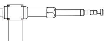 Correct adjustment of the dipole elements | 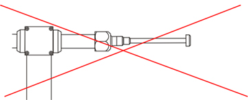 Wrong adjustment of the dipole elements |
For a good mounting, the telescopic elements have to be inserted minimum 10 mm into the mounting tube.
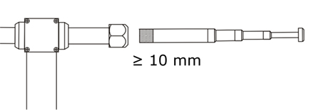
| Table 1: Technical data depending on the element length LE | ||||||
| Element Length | Half-wave resonance | Frequency of maximum gain | Isotropic Gain | Antenna Factor | Bandwidth with 0.5 dB gain decay | Bandwidth with 1 dB gain decay |
| L E | fλ/2 | f gimax | gi | AF | B[-0.5 dB] | B[-1 dB] |
| [mm] | [MHz] | [MHz] | [dBi] | [dB/m] | [MHz] | [MHz] |
| 500 | 300 | 300 | 0.68 | 19.09 | 287 - 334 | 278 - 348 |
| 375 | 400 | 404 | 1.24 | 21.11 | 376 - 432 | 364 - 450 |
| 300 | 500 | 496 | 1.07 | 23.06 | 452 - 528 | 440 - 554@@ |
| 250 | 600 | 594 | 1.05 | 24.65 | 554 - 654 | 530 - 697 |
| 215 | 698 | 700 | 1.12 | 26.01 | 646 - 762 | 620 - 800 |
| 190 | 789 | 788 | 1.02 | 27.13 | 722 - 878 | 700 - 1000 |
| 174 | 862 | 942 | 0.95 | 28.75 | 782 - 1024 | 740 - >1150 |
| Telescopic El. Removed = 120 mm | 1250 | 1150 | 1.04 | 30.40 | 1022 - >1200 | 961 - >1200 |
Since unwanted reflections are apparent in all practical applications, the tabular values have been determined using a multiple averaging technique (different distances, different angles of the H-plane pattern, height variation). To obtain best measurement results the mast / adapter should be as small as possible
| Schwarzbeck UHA 9105 Specifications | |
| Frequency Range | 300 - 1000 (1100) MHz |
| Dipole Element Extension range | 120 / 174 - 500 mm |
| Holder and Balun Attenuation | 0.4 - 1.5 dB |
| Antenna Factors | 18 - 31 dB/m |
| Antenna Gain over Isotropic | + 1 dBi ... +1.8 dBi |
| Power handling capability | 10 W |
| Half Power Beamwidth, E-Plane | 78 ° |
| Length | 520 mm |
| Weight | 800 g |
| Connector | N - female |
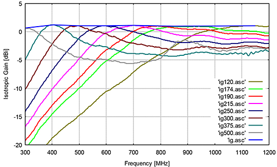
Antenna Factor
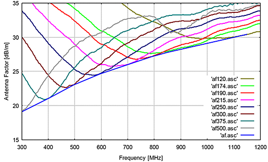
Bandwidth with 0.5 dB gain decay
