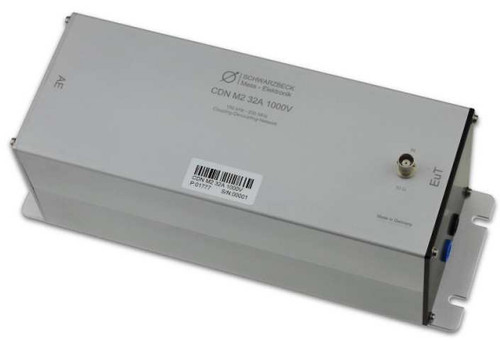
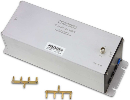
Overview
The Schwarzbeck CDN M2 63A 1000V is a part of the coupling decoupling network series for conducted common mode immunity testing according to IEC 61000-4-6. The CDN M2 63A 1000V complies to IEC 61000-4-6 Annex D.2 and is suitable for immunity testing on unscreened a.c. and d.c. power supply lines (mains lines) with extended voltage rating up to 1000V.
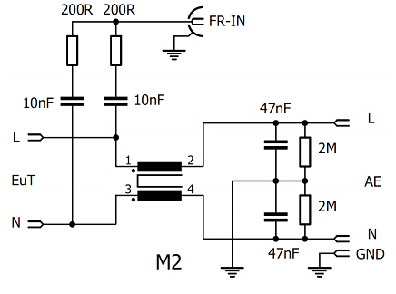
The CDN M2 63A 1000V is intended to inject common mode disturbance signals to power supply or mains lines (unscreened) in the frequency range from 150 kHz to 230 MHz. It can be used for DC voltages up to 1000 V (AC: 400 V) The circuitry schematics is shown in Fig. 5
All CDNs comply to the requirements of IEC 61000-4-6. Each CDN comes with individually measured data and a calibration certificate for the common mode impedance and the voltage division factor. Further typical data can be found in fig. 3 and fig. 4.
A variety of calibration adapters and other accessories are available as options.
Important Note:
The optional shorting adapters must not be used if the CDN is connected to mains!
The capacitors at the AE-side are equipped with 2 M? discharging resistors.
The connection to ground can be accomplished using the ground plane of the CDN. Additionally there is a M4 thread located at the AE side to ground as well as a 4 mm socket to connect the device to ground. The CDN is equipped with 6 mounting notches of 6 mm width at the baseplate
Corresponding terminals are always located in opposite position and can be recognized by the terminal color. They can be used for any phase.
To improve the operational safety the mains voltage-carrying connections are carried out as security sockets. The connectors system is called "Powerline" from Multicontact. The ordering code of the female connectors is:
KBT6AR-N/10-S (for 10 mm² cables)
KBT6AR-N/16-S (for 16 mm² cables)
Caution: The safety connectors come with a selflock to avoid unintentional connection interrupts. Removal of the connector requires therefore a full push in.
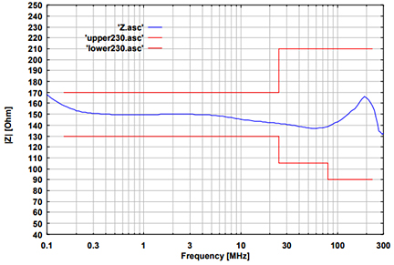 | 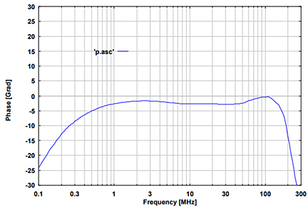 |
| Fig. 1: typ. EuT common mode impedance | Fig. 2: typ. phase EuT-Port, (common mode), informative |
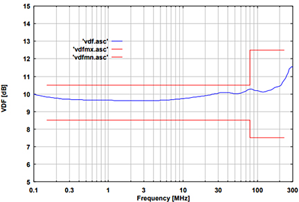 | 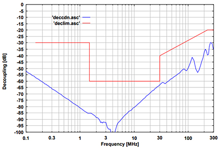 |
| Fig. 3: typ. voltage division factor RF-port to EuT-port | Fig. 4: typ. Isolation between AE and RF-Port, informative |
| Specifications | |
| Frequency range | 150 kHz … 230 MHz |
| Common mode impedance | 150 kHz – 24 MHz: 150 ? ±20 ? 24 MHz – 80 MHz: 150 ? +60 ?/-45 ? 80 MHz – 230 MHz: 150 ? ±60 ? |
| Max. RF-test voltage (emf) | ≤30 V |
| RF-input connector | 50 ? BNC (female) |
| Voltage division factor RF-input – EuT-port | 9.5 dB 150 kHz – 80 MHz: ±1 dB 80 MHz – 230 MHz: +3 dB / - 2 dB |
| Input voltage EuT (AE): Line to ground / line to line | 500 VAC / 1000 VDC 1000 VAC / 2000 VDC |
| Current max. | 63 A (30 min. alternate) |
| Housing material | Aluminium |
| Housing dimensions | 251 x 165 x 167 mm |
| Weight | ca. 3480 g |
| EuT, AE connectors | 6 mm safety male |
| Included accessories | CA 2/6 |
| 3 Pin shorting bar | (2 units included by default) |
| Optional accessories 30 mm distance adapter 50 ? to 150 ? adapter | SR 30/4 SR 100-6W |


